Combinational Circuits
Combinational Circuits. Chapter 3 S. Dandamudi. Introduction Multiplexers and demultiplexers Implementing logical functions Efficient implementation Decoders and encoders Decoder-OR implementations Comparators. Adders Half-adders Full-adders Programmable logic devices


Combinational Circuits
E N D
Presentation Transcript
Combinational Circuits Chapter 3 S. Dandamudi
Introduction Multiplexers and demultiplexers Implementing logical functions Efficient implementation Decoders and encoders Decoder-OR implementations Comparators Adders Half-adders Full-adders Programmable logic devices Programmable logic arrays (PLAs) Programmable array logic (PALs) Arithmetic and logic units (ALUs) Outline S. Dandamudi
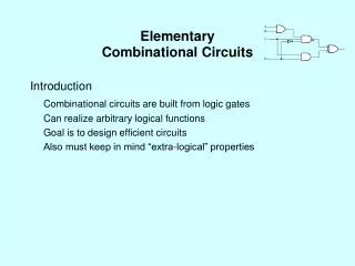
Introduction • Combinational circuits • Output depends only on the current inputs • Combinational circuits provide a higher level of abstraction • Helps in reducing design complexity • Reduces chip count • Example: 8-input NAND gate • Requires 1 chip if we use 7430 • Several 7400 chips (How many?) • We look at some useful combinational circuits S. Dandamudi
Multiplexers • Multiplexer • 2n data inputs • n selection inputs • a single output • Selection input determines the input that should be connected to the output 4-data input MUX S. Dandamudi
Multiplexers (cont’d) 4-data input MUX implementation S. Dandamudi
Multiplexers (cont’d) MUX implementations S. Dandamudi
Multiplexers (cont’d) Example chip: 8-to-1 MUX S. Dandamudi
Multiplexers (cont’d) Efficient implementation: Majority function S. Dandamudi
Multiplexers (cont’d) Efficient implementation: Even-parity function S. Dandamudi
Multiplexers (cont’d) 74153 can used to implement two output functions S. Dandamudi
Demultiplexers Demultiplexer (DeMUX) S. Dandamudi
Demultiplexers (cont’d) 74138 can used as DeMUX and decoder S. Dandamudi
Decoders • Decoder selects one-out-of-N inputs S. Dandamudi
Decoders (cont’d) Logic function implementation S. Dandamudi
Decoders (cont’d) 74139: Dual decoder chip S. Dandamudi
Encoders • Encoders • Take 2B input lines and generate a B-bit binary number on B output lines • Cannot handle more than one input with 1 S. Dandamudi
Encoders (cont’d) • Priority encoders • Handles inputs with more than one 1 S. Dandamudi
Comparator • Used to implement comparison operators (= , > , < , , ) S. Dandamudi
Comparator (cont’d) 4-bit magnitude comparator chip S. Dandamudi
Comparator (cont’d) Serial construction of an 8-bit comparator S. Dandamudi
Adders • Half-adder • Adds two bits • Produces a sum and carry • Problem: Cannot use it to build larger inputs • Full-adder • Adds three 1-bit values • Like half-adder, produces a sum and carry • Allows building N-bit adders • Simple technique • Connect Cout of one adder to Cin of the next • These are called ripple-carry adders S. Dandamudi
Adders (cont’d) S. Dandamudi
Adders (cont’d) A 16-bit ripple-carry adder S. Dandamudi
Adders (cont’d) • Ripple-carry adders can be slow • Delay proportional to number of bits • Carry lookahead adders • Eliminate the delay of ripple-carry adders • Carry-ins are generated independently • C0 = A0 B0 • C1 = A0 B0 A1 + A0 B0 B1 + A1 B1 • . . . • Requires complex circuits • Usually, a combination carry lookahead and ripple-carry techniques are used S. Dandamudi
Adders (cont’d) 4-bit carry lookahead adder S. Dandamudi
Programmable Logic Arrays • PLAs • Implement sum-of-product expressions • No need to simplify the logical expressions • Take N inputs and produce M outputs • Each input represents a logical variable • Each output represents a logical function output • Internally uses • An AND array • Each AND gate receives 2N inputs • N inputs and their complements • An OR array S. Dandamudi
Programmable Logic Arrays (cont’d) A blank PLA with 2 inputs and 2 outputs S. Dandamudi
Programmable Logic Arrays (cont’d) Implementation examples S. Dandamudi
Programmable Logic Arrays (cont’d) Simplified notation S. Dandamudi
Programmable Array Logic Devices • Problem with PLAs • Flexible but expensive • Example • 12 X 12 PLA with • 50-gate AND array • 12-gate OR array • Requires 1800 fuses • 24 X 50 = 1200 fuses for the AND array • 50 X 12 = 600 fuses for the OR array • PALs reduce this complexity by using fixed OR connections • Reduces flexibility compared PLAs S. Dandamudi
Programmable Array Logic Devices (cont’d) Notice the fixed OR array connections S. Dandamudi
Programmable Array Logic Devices (cont’d) • An example PAL (Texas Instruments TIBPAL22V10-10C) • 22 X 10 PAL (24-pin DIP package) • 120-gate AND array • 10-gate OR array • 44 X 120 = 5280 fuses • Just for the AND array • OR array does not use any fuses • Uses variable number of connections for the OR gates • Two each of 8-, 10-, 12-, 14-, and 16-input OR gates • Uses internal feedback through a programmable output cell S. Dandamudi
Programmable Array Logic Devices (cont’d) • MUX selects the input • S0 and S1 are programmed through fuses F0 and F1 S. Dandamudi
Arithmetic and Logic Unit Preliminary ALU design S. Dandamudi
Arithmetic and Logic Unit (cont’d) Final design S. Dandamudi
Arithmetic and Logic Unit (cont’d) 16-bit ALU S. Dandamudi
Arithmetic and Logic Unit (cont’d) 4-bit ALU S. Dandamudi
Summary • Combinational circuits provide a higher level of abstraction • Output depends only on the current inputs • Sample combinational circuits • Multiplexers and demultiplexers • Decoders and encoders • Comparators • Adders • Half-adder • Full-adder S. Dandamudi
Summary (cont’d) • Programmable logic devices • PLAs • PALs • Some more complete sets • Multiplexers • Decoder-OR • PLAs • PALs • Looked at a very simple ALU design Last slide S. Dandamudi