Download

1 / 41
440 likes | 615 Vues
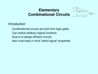
Combinational Circuits. Dr. Bernard Chen Ph.D. University of Central Arkansas. Outline. Boolean Algebra Decoder Encoder MUX. History: Computer and the Rationalist. Modern research issues in AI are formed and evolve through a combination of historical, social and cultural pressures.

E N D
Combinational Circuits Dr. Bernard Chen Ph.D. University of Central Arkansas
Outline • Boolean Algebra • Decoder • Encoder • MUX
History: Computer and the Rationalist • Modern research issues in AI are formed and evolve through a combination of historical, social and cultural pressures. • The rationalist tradition had an early proponent in Plato, and was continued on through the writings of Pascal, Descates, and Liebniz • For the rationalist, the external world is reconstructed through the clear and distinct ideas of a mathematics
History: Development of Formal Logic • The goal of creating a formal language for thought also appears in the work of George Boole, another 19th century mathematician whose work must be included in the roots of AI • The importance of Boole’s accomplishment is in the extraordinary power and simplicity of the system he devised: Three Operations
Three Operations • threebasic Boolean operations can be defined arithmetically as follows. • x∧y=xy • x∨y=x + y − xy • ¬x=1 − x
Boolean function and logic diagram • Boolean algebra: Deals with binary variables and logic operations operating on those variables. • Logic diagram: Composed of graphic symbols for logic gates. A simple circuit sketch that represents inputs and outputs of Boolean functions.
Basic Identities of Boolean Algebra • x + 0 = x • x · 0 = 0 • x + 1 = 1 • x · 1 = 1 (5) x + x = x (6) x · x = x (7) x + x’ = x (8) x · x’ = 0 (9) x + y = y + x (10) xy = yx (11) x + ( y + z ) = ( x + y ) + z (12) x (yz) = (xy) z (13) x ( y + z ) = xy + xz (14) x + yz = ( x + y )( x + z) (15) ( x + y )’ = x’ y’ (16) ( xy )’ = x’ + y’ (17) (x’)’ = x
Gates • Refer to the hardware to implement Boolean operators. • The most basic gates are
Outline • Boolean Algebra • Decoder • Encoder • MUX
Decoder • Accepts a value and decodes it • Output corresponds to value of n inputs • Consists of: • Inputs (n) • Outputs (2n , numbered from 0 2n - 1) • Selectors / Enable (active high or active low)
Decoder Expansion • Decoder expansion • Combine two or more small decoders with enable inputs to form a larger decoder • 3-to-8-line decoder constructed from two 2-to-4-line decoders • The MSB is connected to the enable inputs • if A2=0, upper is enabled; if A2=1, lower is enabled.
Combining two 2-4 decoders to form one 3-8 decoder using enable switch The highest bit is used for the enables
How about 4-16 decoder • Use how many 3-8 decoder? • Use how many 2-4 decoder?
Outline • Boolean Algebra • Decoder • Encoder • Mux
Encoders • Perform the inverse operation of a decoder • 2n (or less) input lines and n output lines
Encoders Perform the inverse operation of a decoder 2n (or less) input lines and n output lines
Accepts multiple values and encodes them Works when more than one input is active Consists of: Inputs (2n) Outputs when more than one output is active, sets output to correspond to highest input V (indicates whether any of the inputs are active) Selectors / Enable (active high or active low) Priority Encoder
Outline • Boolean Algebra • Decoder • Encoder • Mux
Multiplexer (MUX) A selector chooses a single data input and passes it to the MUX output It has one output selected at a time. A multiplexer can use addressing bits to select one of several input bits to be the output.
4 to 1 line multiplexer 4 to 1 line multiplexer 2n MUX to 1 n for this MUX is 2 This means 2 selection lines s0 and s1
Multiplexer (MUX) • Consists of: • Inputs (multiple) = 2n • Output (single) • Selectors (# depends on # of inputs) = n • Enable (active high or active low)
Multiplexers versus decoders • A Multiplexer uses n binary select bits to choose from a maximum of 2n unique input lines. • Decoders have 2^n number of output lines while • multiplexers have only one output line. • The output of the multiplexer is the data input whose index is specified by the n bit code.
Multiplexer Versus Decoder 2-to-4 Decoder 4-to-1 Multiplexer Note that the multiplexer has an extra OR gate. A1 and A0 are the two inputs in decoder. There are four inputs plus two selecs in multiplexer.
Cascading multiplexers Using three 2-1 MUX to make one 4-1 MUX F
Example: Construct an 8-to-1 multiplexer using 2-to-1 multiplexers. I0 I1 I2 I3 F 2-1 MUX S E I4 I5 S2 E I6 I7
Example : Construct 8-to-1 multiplexer using one 2-to-1 multiplexer and two 4-to-1 multiplexers
Quadruple 2-to-1 Line Multiplexer Used to supply four bits to the output. In this case two inputs four bits each.