Download
1 / 13
130 likes | 624 Vues
PicoRadio RF Transmitter & Group Update Yuen Hui Chee Prof. Jan Rabaey University of California, Berkeley BWRC Winter Retreat 13 Jan 2005 PicoRadio RF Quartet Brian Otis Ultra-low power receiver architectures RF MEMS/CMOS co-design techniques Yuen-Hui Chee

E N D
PicoRadio RF Transmitter& Group Update Yuen Hui Chee Prof. Jan Rabaey University of California, Berkeley BWRC Winter Retreat 13 Jan 2005
PicoRadio RF Quartet Brian Otis • Ultra-low power receiver architectures • RF MEMS/CMOS co-design techniques • Yuen-Hui Chee • Ultra-low power transmitter architectures • Antenna techniques • Nathan Pletcher • Reactive Radio architectures • Low voltage RF design • Simone Gambini • Ultra-low power A/D converters
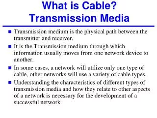
Sleeping nodes Peer to Peer link Multi-hops link Broadcast Wireless Sensor Networks (WSN) – A New Radio Environment • Dense network of nodes over an area • 100’s to 1000’s of nodes • Distance between nodes ≤ 10m1 • Ad-hoc communication • Multi-hops • Peer to peer communications • Low data throughput • Small packet size • Low data rate • Bursty traffic 1 IEEE 802.15.4-2003 std
Available Power1 Power Size Cost External Passives CC2420 Radio2 Challenges System Integration 1S. Roundy, Energy Scavenging for Wireless Sensor Networks, Kluwer Academic Publishers, 2003 2Chipcon datasheets
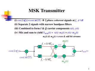
MICROS1 TX Frequency Synthesizer 12mW (40%) Modulator+DAC 0.54mW (2%) Mixer 3.06mW (10%) Power Amplifier 14.4mW (48%) Total: 30mW = 3.3% Current-State-of-the-Art Transmitter MICROS1 Transmitter Issues • Circuit power >> Radiated power • High overhead • Power hungry frequency synthesizer • Inefficient power amplification Traditional transmitter architecture NOT suitable for PicoRadio because it has excessive energy overhead. 1P. Choi et. al, ISSCC 2003
Direct Modulation Transmitter • Direct Modulation • Eliminates I/Q channels less overhead power • No power hungry mixers • RF MEMS based oscillator • Provides a low power frequency reference • Fast startup time • Simple modulation schemes • On-off keying “Lean” transmitter is suitable for low power, low data rate applications
Sub-100W Ultra-Low Power Oscillator Ultra-Low Power 1.9GHz FBAR Oscillator • Consumes a minimal power of 89W • Low Power Design Techniques • Use high Q FBAR resonator • Sub-threshold operation • Low supply voltage • Complementary devices to share bias current • Good phase noise performance • –120dBc/Hz at 100kHz offset FBAR CMOS
Transmitter Implementation Transmitter Performance Summary More details (including Rx) will be presented in ISSCC 2005
Radiated Power ~ Circuit Power Wireless Sensor Networks (WSN) Low Complexity Transmitter Circuit Efficiency Perspective Radiated Power 1W Radiated Power >> Circuit Power Wireless LAN, Cellular High Complexity Transmitter PA Efficiency 100mW 10mW 1mW 100uW Data Rate / Spectral Efficiency Design Principles of Low Power Energy Efficient Transmitter: Simplicity and Co-design
1.9 GHz Active Antenna TX Oscillator 0.36mW (20%) Antenna 0.03mW (1%) Power Amplifier 1.43mW (79%) Total: 1.8mW = 52% CMOS + FBAR PILA Antenna Solar Cell What’s Next: Towards sub-100µW Transceiver Active Antenna Transmitter ST 0.13m CMOS
What’s Next: Towards sub-100µW Transceiver Ultra-low power digital controlled oscillator (DCO) • Nominal power ~ 100µW with 0.5V supply • Bondwire inductor or on-chip inductor • 200MHz tuning range @ 500kHz resolution using 9 bits capacitive bank • Utilize this low power DCO in a reactive radio receiver N. Pletcher
What’s Next: Towards sub-100µW Transceiver • 16MHz micromachined resonators – SiGe structural layer, low temp processing Integrated Silicon Clocks 1µW Low Power Osc 100µW Low Phase Noise Osc B. Otis, N. Pletcher, E. Quévy