Download
1 / 11
110 likes | 243 Vues
This report outlines the current status of the design and production of stainless steel cooling lines at LAPP, detailing production readiness, testing results, and upcoming installation steps. 14 A sidelines are 95% complete and scheduled for bending in W16, while isolation testing shows 28 elements with 26 validated. The splitter boxes' design is nearly finished, and temporary models will assist in the upcoming welding phase. Safety measures for fitting protection and scenarios for repairs are outlined, along with planned delivery schedules for essential components.

E N D
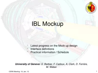
IBL - LAPP Cooling lines Design and production status and schedule Installation LAPP team Jacky Ballansat, Jean-Philippe Baud, Patrick Baudin, Pierre-Yves David, Pierre Delebecque, Sabine Elles, Nicolas Massol, Thibaut Rambure, Theodore Todorov, TamerYildizkaya
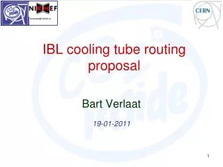
Design and production status • Stainless steel cooling lines production • 14 A sidelines 95% ready (last adjustments on the template (deliveredW16), final bending in the Splitter box region and ends lenghadjustments to bedone) • 14 C sidelines to bebent(W16)
Design and production status • Isolators • 28 elementstested / 26 validated (all at room temperature 150 bars He and 3 at cold) – 10 % failed
Design and production status • Splitter boxes A and C sides • Design almostfinished (delay due to changes askedafter the review / isolations) • Delivery of the final modelsplannedW17 • Temporary plastic model willbeproduced for adjustments and welding phases (W16)
Design and production status • Welding stands • 2 tables A and C sides to bedelivered and mountedW16-W17 • Inlet/outlet connexion (metalic version) deliveredW18 – Plastic version shouldbeavailableW16-W17 for adjustments
Design and production status • Transportation toolings • 2 toolings A and C sides to bedelivered and mountedW16-W17
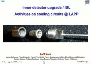
Fitting protection and repair scenarii • 1- Protection of the fittings an reability • All the fittings have a cap protection • Beforeanyassembly and tightening the cone and the sphereiscleanedwith alcool and a visual inspection isdone • The more critical part is the sphere, located on a dismountable part (outside) • Hundredsmounting/dismounting have been performedwithoutany issue (LAPP and SR1) • All the fittingpassed the leak tests withsignalslessthat 10-8 mbar.l.s-1 @ 20 bars He (specis 10-5 mbar.l.s-1 @1 bar) • Whenwe first try to damage the fitting for the repair test the leaklevelwastoolow (10-7 mbar.l.s-1) so the technicianhad to scratch the surfaces once again.
Fitting protection and repair scenarii • 2- Repair scenarii • First step In case of issue : the torque canbeincreased up to 6 N.m • Second step : put some glue between the sphere and the cone. The samplespassed the leak tests before irradiation but not after : conditions of the irradiation to beclarified. • Thirdpossibility : using a specialmetalicpieceused a asealbetween the sphere and the cone (C.F Eric) Gluingtool
Installation – Transportation and assembly • Need a time slot (half a day) to check the transportation and flexible line deployment