Download
1 / 24
240 likes | 507 Vues
RBSP EFW SOC and ConOps. Science Operations Center and Concept of Operations (SOC and ConOps) John Bonnell Space Sciences Laboratory University of California, Berkeley. EFW SOC and ConOps Outline. Science Operations Center (SOC) Requirements Organization Description: Data Products

E N D
RBSP EFWSOC and ConOps Science Operations Center and Concept of Operations (SOC and ConOps) John Bonnell Space Sciences Laboratory University of California, Berkeley EFW INST+SOC PDR
EFW SOC and ConOpsOutline • Science Operations Center (SOC) • Requirements • Organization • Description: • Data Products • Data Processing Flow • Development: • Schedule and Milestones • Test Plan • Status • EFW Concept of Operations (ConOps) • Instrument Commissioning: • Turn-On and Check Out • Boom Deploys • Nominal Operations: • Conditions for Nominal Operations • State-of-Health Monitoring and Trending • Commanding and Day-to-Day Operations EFW INST+SOC PDR
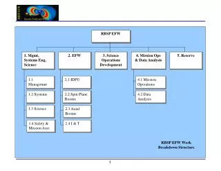
EFW SOCRequirements • The EFW SOC allows the EFW SOC and Science teams to: • Process and distribute EFW science data in a timely, accurate, and configuration-controlled fashion. • Efficiently command and control the EFW instrument, both during ground testing and on-orbit operations. • Governing documents: • RBSP Mission Requirements Document. • RBSP Data Management Plan. • RBSP EFW SOC Requirements Document. • RBSP EFW SOC Software Development Plan. EFW INST+SOC PDR
EFW SOCOrganization • The EFW SOC will be: • Developed at UCB. • Hosted from UCB. • UCB has played a similar role on previous missions: • CRRES, Polar, FAST, THEMIS. • EFW Instrument I&T occurs at UCB, and SOC development builds on the GSE required to support that effort: • GSE→Test SOC→FLT SOC. EFW INST+SOC PDR
EFW SOCData Products EFW INST+SOC PDR
EFW SOCTop-Level Data Processing Diagram EMFISIS SOC MAG data OTHER RBSP and GEOPHYSICAL DATA Sources RBSP MOC CTG-CTG SOC-NRT SOC-PDP SDC-MDP SDC-MAG SDC-ODP SDC-BSEL EFW Supporting DATA ARCHIVES: EMF-MAG STATE MOC OGPD SOC-logs EFW Instrument DATA ARCHIVES: SOH L0+, L1, L2, QL, CAL, L3+ SDC-DVAL SDC-CAL SDC-SDA RBSP EFW SOC Command-Telemetry-Ground Support (CTG) and Science Data Center (SDC) elements. EFW INST+SOC PDR
EFW SOCData Processing Organization • SOC is divided into two parts: • Command, Telemetry, and Ground Support (CTG). • Science Data Center (SDC) • CTG consists of a single CSCI, CTG. • SDC consists of 9 CSCIs: • NRT – Near-real Time data processing and display. • METUTC -- MET↔UTC Time Conversion • PDP – Processed Data Production. • DVAL – Data Validation • BSEL – Burst Data Selection • MDP – MOC Data Products Processing. • MAG – MOC and EMFISIS Data Products Processing. • ODP – Other RBSP and Geophysical Data Products Processing. • SDA – Science Data Analysis. • CAL – EFW Calibration Parameter Production. EFW INST+SOC PDR
EFW SOCCTG Block Diagram GSE EFW INST+SOC PDR
EFW SOCNRT Block Diagram RBSP MOC EFW SOC CTG Near-Real Time Data Acquisition, Processing, and Display (Science and SOH) MOC L0 to SOC L0+ processing EFW L0+ Archive L0+ to L1 Processing EFW L1 Archive NRT Data Analysis And Display Autonomous Operation SOC and SCI team input required External Process or Resource EFW INST+SOC PDR
EFW SOCPDP and DVAL Block Diagram EFW EMF-MAG Archive MOC L0 to SOC L0+ processing L1 to L2 Processing L0+ to L1 Processing RBSP MOC STATE (EPHEM/ATT) Archive EFW L0+ Archive EFW L1 Archive EFW L2 Archive (internal) CAL Archive EFW QL Archive (internal) EFW L2 and QL Archive (ext. access) L2 and QL transfer to external access L2 and QL Validation QL Data and Plot Production. Processed Data Products (PDP and DVAL): Acquisition, Production, Validation, and Delivery. Autonomous Operation SOC and SCI team input required External Process or Resource C T G EFW INST+SOC PDR
EFW SOCBSEL Block Diagram EFW EMF-MAG Archive EFW Burst (B1 and B2) Ground Selection RBSP MOC EFW SOC CTG MET↔UTC Conversion STATE (EPHEM/ATT) Archive EFW Command Archive OTHER Data Acq. EFW QL Archive (internal) EFW L2 Archive (internal) OTHER Data Sources Burst Selection ( BSEL): Generation, Validation, Delivery, and Archiving. Autonomous Operation SOC and SCI team input required External Process or Resource EFW INST+SOC PDR
EFW SOCMDP and MAG Block Diagrams RBSP MOC RBSP MOC QuickLookMAG data EMFISIS SOC MAG data MOC Data Products Retrieval (non-Data, non-SOH) MOC Data Products Archive EMF-MAG Data Acq ATT/EPHEM to STATE Processing Other MOC Data Products (OMDP) Processing SCLK Kernel Processing EFW EMF-MAG Archive SOH Archive EFW OMDP Archive EFW STATE Archive EFW SCLK Archive SCLK (MET↔UTC), MOC Data Products and MAG Data Processing: Retrieval, Validation, Processing, and Archiving. Autonomous Operation SOC and SCI team input required External Process or Resource EFW INST+SOC PDR
EFW SOCSDA and CAL Block Diagrams EFW EMF-MAG Archive STATE (EPHEM/ATT) Archive CAL Archive STATE (EPHEM/ATT) Archive EFW EMF-MAG Archive Plasma Data (eg. ECT-HOPE Vion) L2 to L3+ Processing (TDAS or SDT) L1 to L2 Processing (TDAS or SDT) CAL Archive CAL Archive CAL Production EFW L1 Archive EFW L2 Archive (internal or external) EFW SOH/HSK Archive EFW L1 Archive External Users (ISTP CDF End Users) EFW L2 Archive Science Data Analysis (Internal and External) CAL Parameter Estimation and Production Autonomous Operation SOC and SCI team input required External Process or Resource EFW INST+SOC PDR
EFW SOCDevelopment Plan: Schedule and Milestones EFW INST+SOC PDR
EFW SOCTest Plan • Detailed GSE-SOC test plan under development (due Q2 or Q3, 2009; supports SDP Phase II). • CSCI elements will be tested in isolation to establish basic functionality (test cases; error cases and signaling). • Example: phased introduction of DCB functions and testing using GSE. • Elements are brought together into full modules and fed instrument data from known sensor excitations to verify module-level functionality and requirements fulfillment. • Example: basic instrument functional tests during I&T. • End-to-end testing at each stage of integration to weed out problems early. • Example: testing of complete PDP chain as early as possible during Phase D using data from SC I&T and environmental tests. EFW INST+SOC PDR
EFW SOCCurrent Status • Current Status consistent with Phase I Development (Core Instrument Support through GSE): • GSE module can: • Communicate with the DCB via the SC Emulator and GSEOS • Raw data. • CCSDS packetized data. • Display received data in hexdump format. • Detect errors in CCSDS/ITF data. • Generate PPS/SP signals with SC Mini-Emulator. • Upcoming efforts include (Nov 2008): • Development of board-level GSE support (BEB and BEB SciCal esp.). • Modification of existing NRT IDL modules for EFW packet formats. EFW INST+SOC PDR
EFW ConOpsInstrument Commissioning • EFW Commissioning consists of two phases: • Initial instrument turn on and check out. • Radial and axial boom deploys. • May occur at RBSP MOC (using Test SOC) or at EFW SOC (using Flight SOC). • Turn-On and Checkout consists of stowed functional tests (duplicates of SC-level I&T procs and data). EFW INST+SOC PDR
EFW ConOpsInstrument Commissioning: Radial Booms Deploy • Initial EFW boom deploy plan already developed: RBSP_EFW_TN_003C_EFW_BoomDeploySequence.doc. • Boom deploy power controlled by MOC (SC service). • Boom deploy commanding through EFW SOC (test or flight). • Spin rate changes during staged, pairwise boom deploy illustrated below. • Spin rate vs. boom stroke and time during deploy used to monitor state of deploy and abort, if required. • Baseline 13-day parallel deploy schedule between both observatories; required durations based on recent THEMIS-EFI experience (parallel ops on THD and THE, June 2007). Fine wire unfurling EFW INST+SOC PDR
EFW ConOpsInstrument Commissioning: Axial Booms Deploy • Axial boom deploy occurs after radial boom deploy is complete, and observatory mass properties and dynamics confirmed (typically no significant delay required). • Axial booms deployed singly, in stages using motor deploy system to ≈5-m stroke (≈10-m tip-to-tip). • Final deploy lengths trimmed in roughly 10-cm increments using Survey axial E-field and SC potential estimates to reduce common-mode signal (expected duration of trim phase is 2 weeks, but is outside of commissioning phase). EFW INST+SOC PDR
EFW ConOpsValidity Conditions for Nominal Operations • Sensors Illuminated -- All EFW sensors illuminated (goal for aft axial sensor). • Attitude Known -- Post-processed Observatory attitude (spin axis pointing and spin phase) known to accuracy better than 3 deg. • Ephemerides Known -- Post-processed Observatory position and velocity known to accuracy better than (10 km, 30 m/s, 0.1 deg; 3-sigma). • Booms Settled -- EFW radial booms within 0.5 deg of nominal position. • DC B-Field Known – Post-Processed DC B-field known to accuracy better than 1%. • EFW-MAG-SCM Relative Orientation Known – Post-processed relative orientation of EFW, MAG, and SCM sensor axes known to better than 2 degrees. EFW INST+SOC PDR
EFW ConOpsInstrument Health and Status Monitoring • Instrument State-of-Health (SOH) monitored through near-real-time or playback engineering data via the SOC-CTG. • SOH compared against red/yellow limit database. • Off-Nominal conditions leads to: • Notification of EFW SOC personnel (page, e-mail). • Issuance of scripted commands, for certain, well-known off-nominal conditions (example: CRRES DDD-false commanding and resets). • Long-term trending and storage of SOH data: • New solution in GSEOS as part of CTG efforts or… • Incorporation into existing UCB MOC BTAPS database (decision: part of Phase III development, 2010 time frame). EFW INST+SOC PDR
EFW ConOpsNormal On-Orbit Operations • Commanding • Complete instrument state (sensor biasing and data collection) set by ~50 commands. • Instrument configuration changes infrequently (~1/few weeks, after initial commissioning phase). • ~daily commanding to support ground selection of burst segments as needed. • ~monthly Sensor Diagnostic Tests (bias sweeps) to confirm and optimize instrument biasing. • Data Management • 12 kbps daily average: • ~ 5 kbps continuous Survey data (32 S/s E and V; auto- and cross-spectral data products). • ~ 7 kbps Burst1 and Burst2 data (0.5 and 16 kS/s E, V, and SCM data). • Burst Management • Higher-rate waveform data (E, V, and SCM) collected continuously and banked into SDRAM and FLASH in seconds to minutes long segments (many days of B1 storage; many hours of B2 storage). • Each segment tagged with “Burst Quality” computed on-board from DC or AC fields data cues (DC Spin-Fit E; SC Potential; Filter Bank AC E or B). • B1 playback is through ground selection based on Survey data and other data sources (geophysical indices, etc.); on-board with Burst Quality allows for autonomous selection and playback, as needed (vacations, illness, ennui, etc.). • B2 survival and playback selection on-board is based on Burst Quality; playback selection includes option for ground selection based on Survey data and other data sources (geophysical indices, etc.). • B1 and B2 support for time-tagged campaign modes available as well (e.g. BARREL support). • Inter-Instrument Burst Data • EFW message includes axial sensor status (illuminated/eclipsed), sensor sweep status (static/sweeping), and current burst-valuation algorithm ID and value. EFW INST+SOC PDR
EFW ConOpsCommand Generation • EFW-SOC shall generate commands by reference to UTC, as well as MOC data products (predicted ephemerides, etc.) and other data assets (e.g.. Geomagnetic indices). • EFW commands shall be validated as needed by running command load on EFW TestBed (ETU) and verifying appropriate change of state, data production, and instrument configuration. • Command validation shall occur prior to transmission of command load from EFW-SOC to RBSP-MOC. • Verification of current MET↔UTC SCLK Kernel shall occur prior to translation of EFW commands from UTC to MET. • Command receipt will be verified after transmission using standard MOC data products. EFW INST+SOC PDR
This page intentionally almost blank EFW INST+SOC PDR