Internet Overview
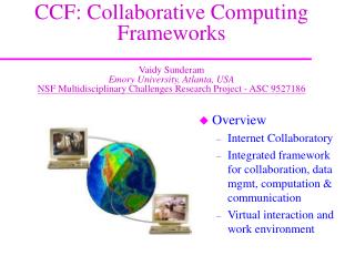
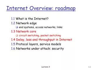
Explore the network of networks that form the internet, from hardware devices to software protocols like TCP, IP, HTTP, & FTP. Learn about routers, end-systems, and the client/server model. Understand the transmission of data through the internet via packet-switching and circuit switching.

Internet Overview
E N D
Presentation Transcript
Internet Overview Stuart D. Milner, Ph.D. Clark School of Engineering Institute for Systems Research April 9 and 11, 2002 Acknowledgement: The briefing slides from: Kurose, J.F. and Ross, K.W. Computer Networking: A Top Down Approach Featuring the Internet. Addison-Wesley, 2001.
> 50M connected computing devices ( >100M users): hosts, end-systems pc’s workstations, servers PDA’s, phones Emerging convergence of telephony, wireless (“bluetooth” and 802.11); and deeply embedded systems (e.g, toasters, sensors) running network apps communication links fiber, copper, radio, satellite,wireless optical routers: forward packets (chunks) of data thru network router workstation server mobile local ISP regional ISP company network What’s the Internet: Hardware and Software
protocols: control sending, receiving of msgs e.g., TCP, IP, HTTP, FTP, PPP Internet: “network of networks” hierarchical topology of networks connected via backbones public Internet versus private intranet Internet standards IETF: Internet Engineering Task Force What’s the Internet: Hardware and Software router workstation server mobile local ISP regional ISP company network
end systems (hosts): run application programs e.g., WWW, email at “edge of network” client/server model client host requests, receives service from server e.g., WWW client (browser)/ server; email client/server peer-peer model: host interaction symmetric e.g.: teleconferencing The network edge:
mesh of interconnected routers the fundamental question: how is data transferred through net? circuit switching: dedicated circuit per call: telephone net packet-switching: data sent thru net in discrete “chunks” The Network Core
TCP connection reply. Get http://isr.umd.edu/cschn <file> time What’s a protocol? Examples: Routers: packet path from source to destination network interface card: control flow of bits on the “wire” Host computers: control congestion and rate at which pkts. transmitted between sender and receiver Everywhere in the Internet! TCP connection req.
application: supporting network applications ftp, smtp, http transport: host-host data transfer, congestion control, segmentation tcp, udp network: routing of datagrams from source to destination ip, routing protocols link: data transfer between neighboring network elements ppp, ethernet physical: bits “on the wire” application transport network link physical Internet protocol stack
E.g.: transport take data from app add addressing, reliability check info to form “datagram” send datagram to peer wait for peer to ack receipt network link physical application transport network link physical application transport network link physical application transport network link physical application transport network link physical data data data ack Layering: logical communication transport transport
M M H H H H H H H H H H H H t t t t l n l t n n t n M M M M application transport network link physical application transport network link physical M M Protocol layering and data: protocol data units (PDUs) Each layer takes data from above (SERVICE MODEL) • adds header information to create new data unit • passes new data unit to layer below source destination message segment datagram frame
SERVICE MODEL • Layer n-1 offers SERVICES to Layer n • For example: • Layer n-1 guarantees that n-PDU will arrive without error at Layer n in the destination within 1 second • Or, Layer n-1 might only guarantee that n-PDU will eventually arrive at destination without assurances about error
Application: communicating, distributed processes running in network hosts in “user space” exchange messages to implement app e.g., email, file transfer, the Web Application-layer protocols one “piece” of an app define messages exchanged by apps and actions taken user services provided by lower layer protocols application transport network data link physical application transport network data link physical application transport network data link physical I. Applications and application-layer protocols
Typical network app has two pieces: client and server request reply application transport network data link physical application transport network data link physical Client-server paradigm Client: • initiates contact with server (“speaks first”) • typically requests service from server, • for Web, client is implemented in browser; for e-mail, in mail reader Server: • provides requested service to client • e.g., Web server sends requested Web page, mail server delivers e-mail
API: application programming interface defines interface between application and transport layer socket: Internet API two processes communicate by sending data into socket, reading data out of socket interface between application and transport layers Q: how does a process “identify” the other process with which it wants to communicate? IP address of host running other process “port number” - allows receiving host to determine to which local process the message should be delivered # 80 for HTTP # 25 for SMTP RFC 1700 Application-layer protocols (cont). … more on this later.
http: hypertext transfer protocol Web’s application layer protocol client/server model client: browser that requests, receives, “displays” Web objects server: Web server sends objects in response to requests The Web: the http protocol http request PC running Explorer http response http request standard Web server http response Mac running Navigator
Suppose user enters URL www.someSchool.edu/someDepartment/home.index 1a. http client initiates TCP connection to http server (process) at www.someSchool.edu. Port 80 is default for http server. http example (contains text, references to 10 jpeg images) 1b.http server at host www.someSchool.edu waiting for TCP connection at port 80. “accepts” connection, notifying client 2.http client sends http request message (containing URL) into TCP connection socket 3.http server receives request message, forms response message containing requested object (someDepartment/home.index), sends message into socket time
5. http client receives response message containing html file, displays html. Parsing html file, finds 10 referenced jpeg objects http example (cont.) 4.http server closes TCP connection. 6.Steps 1-5 repeated for each of 10 jpeg objects time
Authentication goal: control access to server documents stateless: client must present authorization in each request authorization: typically name, password authorization: header line in request if no authorization presented, server refuses access, sends WWW authenticate: header line in response usual http request msg + Authorization:line usual http request msg + Authorization:line usual http response msg usual http response msg time User-server interaction: authentication server client usual http request msg 401: authorization req. WWW authenticate: Browser caches name & password so that user does not have to repeatedly enter it.
ftp client contacts ftp server at port 21, specifying TCP as transport protocol two parallel TCP connections opened: control: exchange commands, responses between client, server. “out of band control” data: file data to/from server ftp server maintains “state”: current directory, earlier authentication TCP control connection port 21 TCP data connection port 20 FTP client FTP server ftp: separate control, data connections
Internet hosts, routers identified by: host “name”, e.g., gaia.cs.umass.edu - used by humans IP address (32 bit) - used for addressing datagrams Directory Service translates host names to IP addresses Domain Name System: distributed database implemented in hierarchy of many name servers application-layer protocol host, routers, name servers to communicate to resolvenames (address/name translation) note: core Internet function implemented as application-layer protocol complexity at network’s “edge” commonly used by other application layer protocols (e.g., http) DNS: Domain Name System
contacted by local name server that can not resolve name root name server: contacts authoritative name server if name mapping not known gets mapping returns mapping to local name server ~ dozen root name servers worldwide Root name servers
host surf.eurecom.fr wants IP address of gaia.cs.umass.edu 1. Contacts its local DNS server, dns.eurecom.fr 2.dns.eurecom.fr contacts root name server, if necessary 3. root name server contacts authoritative name server, dns.umass.edu, if necessary local name server dns.eurecom.fr Simple DNS example root name server 2 4 3 5 authoritative name server (for all hosts in umass.edu domain) dns.umass.edu 1 6 requesting host surf.eurecom.fr gaia.cs.umass.edu
a host-local, application-created/owned, OS-controlled interface (a “door”) into which application process can both send and receive messages to/from another (remote or local) application process socket Socket programming How client/server applications/processes communicate using sockets Socket API • introduced in BSD4.1 UNIX, 1981 • explicitly created, used, released by apps • client/server paradigm • implementation of a protocol defined by an RFC (e.g., FTP, Netscape) • “proprietary” client server application not necessarily conforming to an RFC (MSN and Erols security/authentication?) • two types of transport service via socket API: • unreliable datagram --UDP • reliable, byte stream-oriented -- TCP
process process TCP with buffers, variables TCP with buffers, variables socket socket Socket-programming using TCP Socket: a door between application process and end-end-transport protocol (UCP or TCP) TCP service: reliable transfer of bytes from one process to another controlled by application developer controlled by application developer controlled by operating system controlled by operating system internet host or server host or server
create socket, connect to hostid, port=x create socket, port=x, for incoming request: clientSocket = Socket() welcomeSocket = ServerSocket() TCP connection setup wait for incoming connection request connectionSocket = welcomeSocket.accept() send request using clientSocket read request from connectionSocket write reply to connectionSocket read reply from clientSocket close connectionSocket close clientSocket Client/server socket interaction: TCP Server (running on hostid) Client
provide logical communication between app’ processes running on different hosts transport protocols run in end systems transport vs network layer services: network layer: data transfer between end systems transport layer: data transfer between processes relies on, enhances, network layer services application transport network data link physical application transport network data link physical network data link physical network data link physical network data link physical network data link physical network data link physical logical end-end transport II. Transport services and protocols
Internet transport services: reliable, in-order unicast delivery (TCP) congestion flow control connection setup unreliable (“best-effort”), unordered unicast or multicast delivery: UDP services not available: real-time bandwidth guarantees reliable multicast application transport network data link physical application transport network data link physical network data link physical network data link physical network data link physical network data link physical network data link physical logical end-end transport Transport-layer protocols
multiplexing/demultiplexing: based on sender, receiver port numbers, IP addresses source, dest port #s in each segment recall: well-known port numbers for specific applications Multiplexing: Multiplexing/demultiplexing gathering data from multiple app processes, enveloping data with header (later used for demultiplexing) 32 bits source port # dest port # other header fields application data (message) TCP/UDP segment format
Source IP: C Dest IP: B source port: x dest. port: 80 Source IP: C Dest IP: B source port: y dest. port: 80 Source IP: A Dest IP: B source port: x dest. port: 80 source port:23 dest. port: x source port: x dest. port: 23 Multiplexing/demultiplexing: examples Web client host C server B host A 2 processes, 2 source ports 1 app. port use: simple telnet app Web server B Web client host A port use: Web server
“no frills,” “bare bones” Internet transport protocol “best effort” service, UDP segments may be: lost delivered out of order to app connectionless: no handshaking between UDP sender, receiver each UDP segment handled independently of others Why is there a UDP? no connection establishment (which can add delay) simple: no connection state at sender, receiver small segment header (8 B vs. 20 B for TCP) no congestion control: UDP can blast away as fast as desired -- but this is an issue for Internet (p. 180) UDP: User Datagram Protocol [RFC 768]
often used for streaming multimedia apps loss tolerant rate sensitive other UDP uses (why?): DNS SNMP reliable transfer over UDP: add reliability at application layer application-specific error recover! UDP: more 32 bits source port # dest port # Length, in bytes of UDP segment, including header checksum length Application data (message) UDP segment format
full duplex data: bi-directional data flow in same connection MSS: maximum segment size for app layer data (configurable; e.g., 1500B; 512B) connection-oriented: handshaking (exchange of control msgs) init’s sender, receiver state before data exchange flow controlled: sender will not overwhelm receiver point-to-point: one sender, one receiver no concept of multicasting in TCP (see p. 349) reliable, in-order byte stream: no “message boundaries” pipelined: TCP congestion and flow control set window size send & receive buffers TCP: OverviewRFCs: 793, 1122, 1323, 2018, 2581
32 bits source port # dest port # sequence number acknowledgement number head len not used rcvr window size U A P R S F checksum ptr urgent data Options (variable length) application data (variable length) TCP segment structure URG: urgent data (generally not used) counting by bytes of data (not segments!) ACK: ACK # valid PSH: push data now (generally not used) # bytes rcvr willing to accept, used for flow control RST, SYN, FIN: connection estab (setup, teardown commands) Internet checksum (as in UDP, see p. 181)
Congestion: informally: “too many sources sending too much data too fast for network to handle” different from flow control! manifestations: lost packets (buffer overflow at routers) long delays (queueing in router buffers) typically results from overflowing of router buffers as network becomes congested and packets dropped/lost a top-10 problem! Principles of Congestion Control
end-end control (no network assistance) transmission rate limited by congestion window size over segments: TCP Congestion Control Congwin
two “phases” I. slow start II. congestion avoidance important variables: Congwin (in segments) threshold: defines threshold between two slow start phase, congestion control phase “probing” for usable bandwidth: ideally: transmit as fast as possible (Congwin as large as possible) without loss increaseCongwin until loss (congestion) loss: decreaseCongwin, then begin probing (increasing) again TCP congestion control:
exponential increase (per RTT) in window size (not so slow!) loss event: e.g., timeout Slowstart algorithm time TCP Slowstart Host A Host B one segment RTT initialize: Congwin = 1 for (each segment ACKed) Congwin++ until (loss event OR CongWin > threshold) two segments four segments
TCP Congestion Avoidance Congestion avoidance loss occurs /* slowstart is over */ /* Congwin > threshold */ Until (loss event) { every w segments ACKed: Congwin++ } threshold = Congwin/2 Congwin = 1 perform slowstart linear exponential 1 1. TCP Tahoe 2: TCP Reno skips slowstart (fast recovery) after three duplicate ACKs
transport packet from sending to receiving hosts network layer protocols in every host, router three important functions: path determination: route taken by packets from source to dest. Routing algorithms switching: move packets from router’s input to appropriate router output call setup: some network architectures require router call setup along path before data flows network data link physical network data link physical network data link physical network data link physical network data link physical network data link physical network data link physical network data link physical application transport network data link physical application transport network data link physical III. Network layer functions
Graph abstraction for routing algorithms: graph nodes are routers graph edges are physical links link cost: delay, $ cost, or congestion level 5 3 5 2 2 1 3 1 2 1 A D E B F C Routing protocol Routing Goal: determine “good” path (sequence of routers) thru network from source to dest. • “good” path: • typically means minimum cost path • other def’s possible • least cost for A-C is ADEC
Finding least-cost path Given the graph abstraction, the problem of finding the least-cost path from a source to a destination requires identifying a series of links such that: • the first link in the path is connected to the source • the last link in the path is connected to the destination • for all i, the i and i-1st link in the path are connected to the same node • for the least-cost path, the sum of the cost of the links on the path is the minimum over all possible paths between the source and destination. Note: shortest path is, the path crossing the smallest number of links between the source and the destination
Dijkstra’s algorithm net topology, link costs known to all nodes accomplished via “link state broadcast” node knows about costs to directly attached neighbors and learns about topology from broadcasts from other nodes all nodes have same info computes least cost paths from one node (‘source’) to all other nodes gives routing table for that node iterative: after k iterations, know least cost path to k dest.’s Notation: c(i,j): link cost from node i to j. cost infinite if not direct neighbors D(v): current value of cost of path from source to dest. V for given iteration p(v): predecessor node along path from source to v, that is next v (neighbor) N: set of nodes whose least cost path definitively known A Link-State Routing Algorithm for Computing Least-cost Path from One Node to All Other Nodes
5 3 5 2 2 1 3 1 2 1 A D E B F C Dijkstra’s algorithm: exampleEach line in table gives values at end of the iteration D(B),p(B) 2,A 2,A 2,A D(D),p(D) 1,A D(C),p(C) 5,A 4,D 3,E 3,E D(E),p(E) infinity 2,D Step 0 1 2 3 4 5 start N A AD ADE ADEB ADEBC ADEBCF D(F),p(F) infinity infinity 4,E 4,E 4,E
IP address: 32-bit identifier for host, router interface interface: connection between host, router and physical link router’s typically have multiple interfaces host may have multiple interfaces IP addresses associated with interface, not host, router 223.1.1.2 223.1.2.1 223.1.3.27 223.1.3.1 223.1.3.2 223.1.2.2 IP Addressing: introduction 223.1.1.1 223.1.2.9 223.1.1.4 223.1.1.3 223.1.1.1 = 11011111 00000001 00000001 00000001 223 1 1 1 dotted decimal notation
IP address: network part (high order bits) host part (low order bits) What’s a network ? (from IP address perspective) device interfaces with same network part of IP address can physically reach each other without intervening router IP Addressing 223.1.1.1 223.1.2.1 223.1.1.2 223.1.2.9 223.1.1.4 223.1.2.2 223.1.3.27 223.1.1.3 LAN 223.1.3.2 223.1.3.1 • network consisting of 3 IP networks • (for IP addresses starting with 223, • first 24 bits are network address or • prefix) • leftmost 24 bits defines net • address in “/24” notation or network mask
How to find the networks? Detach each interface from router, host create “islands of isolated networks 223.1.3.27 223.1.3.1 223.1.3.2 IP Addressing 223.1.1.2 223.1.1.1 223.1.1.4 223.1.1.3 223.1.7.0 223.1.9.2 223.1.9.1 223.1.7.1 223.1.8.1 223.1.8.0 Interconnected system consisting of six networks 223.1.2.6 223.1.2.1 223.1.2.2 NB. 3 routers interconnected by point-to-point links
IP datagram: 223.1.1.1 223.1.2.1 E B A 223.1.1.2 source IP addr 223.1.2.9 misc fields dest IP addr 223.1.1.4 data 223.1.2.2 223.1.3.27 223.1.1.3 223.1.3.2 223.1.3.1 Dest. Net. next router Nhops 223.1.1 1 223.1.2 223.1.1.4 2 223.1.3 223.1.1.4 2 Getting a datagram from source to dest. routing table in A • datagram remains unchanged, as it travels source to destination • addr fields of interest here
223.1.1.1 223.1.2.1 A E B 223.1.1.2 223.1.2.9 223.1.1.4 223.1.2.2 223.1.3.27 223.1.1.3 223.1.3.2 223.1.3.1 Dest. Net. next router Nhops 223.1.1 1 223.1.2 223.1.1.4 2 223.1.3 223.1.1.4 2 Getting a datagram from source to dest. misc fields data 223.1.1.1 223.1.1.3 Starting at A, given IP datagram addressed to B: • look up net. address of B • find B is on same net. as A • link layer will send datagram directly to B inside link-layer frame • B and A are directly connected
223.1.1.1 223.1.2.1 A E B 223.1.1.2 223.1.2.9 223.1.1.4 223.1.2.2 223.1.3.27 223.1.1.3 223.1.3.2 223.1.3.1 Dest. Net. next router Nhops 223.1.1 1 223.1.2 223.1.1.4 2 223.1.3 223.1.1.4 2 Getting a datagram from source to dest. misc fields data 223.1.1.1 223.1.2.2 Starting at A, dest. E: • look up network address of E • E on different network • A, E not directly attached • routing table: next hop router to E is 223.1.1.4 • link layer sends datagram to router 223.1.1.4 inside link-layer frame • datagram arrives at 223.1.1.4 • continued…..
Dest. next 223.1.1.1 network router Nhops interface 223.1.2.1 E B A 223.1.1 - 1 223.1.1.4 223.1.1.2 223.1.2 - 1 223.1.2.9 223.1.2.9 223.1.1.4 223.1.3 - 1 223.1.3.27 223.1.2.2 223.1.3.27 223.1.1.3 223.1.3.2 223.1.3.1 Getting a datagram from source to dest. misc fields data 223.1.1.1 223.1.2.2 Arriving at 223.1.4, destined for 223.1.2.2 • look up network address of E • E on same network as router’s interface 223.1.2.9 • router, E directly attached • link layer sends datagram to 223.1.2.2 inside link-layer frame via interface 223.1.2.9 • datagram arrives at 223.1.2.2