Investigating Transverse Blow-Up in PSB: Challenges and Strategies for Low-Intensity Beams
270 likes | 382 Vues
This presentation discusses the ongoing studies on transverse blow-up in the Proton Synchrotron Booster (PSB) as part of the CERN-GSI meetings. It evaluates techniques for managing low-intensity beams, emphasizing the significance of transverse and longitudinal beam shaving methods. Key findings include challenges in maintaining emittance and stability during blow-up processes, emphasizing the necessity for effective power limits and beam control strategies. Various experimental approaches are outlined to mitigate particle loss and optimize beam quality, with particular focus on achieving desired emittance for LHC operations.

Investigating Transverse Blow-Up in PSB: Challenges and Strategies for Low-Intensity Beams
E N D
Presentation Transcript
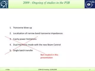
2009 - Ongoing rf studies in the PSB Transverse blow-up Localization of narrow band transverse impedances Cavity power limitations Dual Harmonic mode with the new Beam Control Single batch transfer Not treated in this presentation CERN-GSI meeting 22/09/2009
A. Findlay, B. Mikulec, G. Rumolo Transverse emittance blow-up in PSB Motivation and requirements Past experience Present test Future tests CERN-GSI meeting 22/09/2009
When a low-intensity beam is required is the PSB - below 1 injected turn or 70E10 p - measures need to be taken in order to limit the number of particles. Different approaches can be used: • Sieves in the injection line at 50 MeV reduce the intensity by a factor 5 but cannot be used as they are not maintained anymore. • H, V or Longitudinal shaving can be used, but each methods has its limitations: • H shaving is not very stable (data not yet obtained from OP): fluctuation in the Linac energy and trajectory (CPS field coupling) do not insure a reproducible distribution. It also creates a reduction of the H emittance below the LHC requirements -> it needs blow-up! • V shaving is stable but creates a reduction of the emittance. It needs blow-up . For the LHC beams, blow-up can be achieved in the SPS -up to 400%- (W. Höfle et alii). • Longitudinal shaving is under test (J. Tan & J. Sanchez) but only for very low intensities < 12E10 ppb. The operation is in 2 stages: capture at a low rf voltage + fine shaving with blow-up using a high frequency cavity (C16) and a low main rf voltage (C02 or C04). The second stage creates losses at a relatively high energy (critical issue with L4?). Transverse blow-up in the PSB Motivation and requirements CERN-GSI meeting 22/09/2009
The longitudinal beam shaving works well to obtain a low intensities but creates losses at relatively high energies Transverse blow-up in the PSB Motivation and requirements RF voltage program for longitudinal shaving Courtesy J. Tan Longitudinally shaved beam Beam losses at high energy to be avoided (especially with Linac 4) CERN-GSI meeting 22/09/2009
In brief: transverse blow-up in the PSB could be used 1) after a transverse shaving to recover some lost emittance 2) to release space charge constraints 3) for the CPS MTE* operation or 4) when required for MDs • The actual study in the PSB was aimed at restoring the vertical emittance of a vertically shaved beam of the type LHC25 with an intensity equal to nominal/5, i.e. 162E10p/5 = 32E10 p • The exercise was to increase the normalized RMS emittance (2σ) after vertical shaving from 1 .um to 2 .um (+100%) in the vertical plane. • The measurements were made using SEM grids on the PSB extraction line towards the dump at 1.4 GeV • * : For the CPS MTE, a great H normalized emittance is required (>11 .mm.mrad/1σ) together with a small V emittance (< 5 .mm.mrad /1σ). This is presently achieved by crossing a transverse horizontal resonance in the PSB. The tests in the CPS to achieve blow-up have not yet been very successful (hollow distribution) Transverse blow-up in the PSB Motivation and requirements CERN-GSI meeting 22/09/2009
In October 2005 a blow-up test has been achieved in the horizontal plane (A. Findlay, G. Rumolo). SETUP: A wideband (20 MHz) noise generator was plugged into an excitation input of the TFB system. The loop bandwidth was actually limited to 13 MHz by a filter (the remaining of the open loop has a cutoff frequency of 100 MHz). RESULTS The experience was not successful: using the full power (2 x 100W) during the entire cycle (530ms) didn’t lead to any measurable result. INTERPRETATION OF THE RESULTS 2 X 100 W over 13 MHz means very little energy per betatron line The arbitrary phase of the excitation over many betatron lines may limit the efficiency (not yet analyzed) Other method: transverse resonances crossing This method gives good results but sometimes not very stable (fluctuations in the optics or fluctuation of the Betatron frequency distribution?) and creates losses at high energies (to be checked further). Transverse blow-up in the PSB Past experience CERN-GSI meeting 22/09/2009
GLOBAL STRATEGY: Limit the excitation bandwidth to have, for the same global power, more power per betatron line… and to reduce counterproductive (?) effects due to the erratic phase distribution along different betatron lines. Increase the gain of the excitation at the very betatron line by making the TFB loop marginally stable. This is achieved by: 1) inverting the loop phase 2) setting the loop gain just below instability 3) setting the Q value in order to have an open loop transfer function real (and negative) at the very betatron line (presently in the PSB, there is no Betatron phase setting within the loop) Transverse blow-up in the PSB Present test |CLTF|=|G/(1+GH)| OLTF = G.H Im IN Σ G OUT ω -1 Re H Freq. ω CERN-GSI meeting 22/09/2009
See logbook 8/9/09 PM, 28/8/09 • LHC25 beam, PLS line 21 • 2.2 turns injected (100E10p) to obtain a reproducible beam (?) • Beam shaved vertically at C305 down to 30E10p and 1 .μm • The vertical blow-up process starts after the end of the shaving at C320. • The objective is to obtain 2 .μm (100% blow-up) • From C320 onwards, Frev increases from 0.72 to 1.746 MHz and Qv from 4.46 to 4.22 => qFrev [0.33 , 0.57 MHz], (1-q)Frev [0.39 , 1.35 MHz], (1+q)Frev [1.05 , 2.13 MHz] , and (2-q)Frev [1.1 , 3.1 MHz] Transverse blow-up in the PSB conditions of present test A 20 MHz wide noise was generated by an Agilent 33250 (?) arbitrary waveform generator. A non ideal band-pass filter was used (this is what we had available) at the output of the generator(1 MHz 1st order high-pass followed by a 6th order, 1.9 MHz low-pass). This total 1 MHz bandwidth allows having 13 times more power spectral density than in the 2005 test. Using a 0.3 -> 0.6 MHz would have been better suited (factor 43). The kicker voltage was observed out of 1:100 attenuator. 100W/50Ω => 100Vpeak => 2Vpp on the scope. The vertical tune was set to 4.21 after C320 to be in the ideal phase relation between Pick-ups and kicker (PU in 4L5 and kicker in 3L1). CERN-GSI meeting 22/09/2009
Transverse blow-up in the PSB conditions of present test CERN-GSI meeting 22/09/2009
Transverse blow-up in the PSB Present test - Results Most reproducible results obtained without C16 => 2 μm obtained 4 shots over 5, the fifth being +/- 5% apart. Even more stable with 1.6 μm. CERN-GSI meeting 22/09/2009
Remarks concerning the test setup. The inverted loop gain was set to a rather low value to avoid an over excitation around C450. If the VTFB loop was closed after C450 there was only very little blow-up. The test with a higher inverted loop gain starting after C450 has not yet been tested (need of an amplifier) This excitation at C450 is interpreted as being a narrow band impedance crossing which explains the activation being a function of the beam intensity. Transverse blow-up in the PSB Present test - Results Traces obtained on a DPO4054 oscilloscope from Tektronix 500 MHz,2.5Gs/s , start pulse = C275 = injection time Top trace : Vertical Pick-up, delta value Bottom trace: Kicker signal (1/100 dividing ratio) = PR Noise over 1-2MHz CERN-GSI meeting 22/09/2009
Transverse blow-up in the PSB Present test - Results Zoom on the vertical excitation during impedance crossing Scope triggered at C495 Top Trace : ΔV signal Middle trace : V kick Bottom trace: Σ beam signal 16 oscillations within the bunch length CERN-GSI meeting 22/09/2009
Temporary conclusion. Pros: This blow-up method is efficient if you have little available power (all the power is exactly used to do the job; especially when not using the noise excitation) Cons: Results are intensity dependant More tests need to be achieved for further clarifications Transverse blow-up in the PSB Present test - Results CERN-GSI meeting 22/09/2009
Use the method in conditions where no narrow band impedance is crossed using a higher loop gain Diminish the noise bandwidth for an improved spectral power density (0.3 ->0.6 MHz) Increase the blow-up excitation by increasing the power of the kicker amplifiers (foreseen in view of higher intensities with Linac 4) Transverse blow-up in the PSB Possible future tests CERN-GSI meeting 22/09/2009
Single tone excitation: In the SPS an efficient blow-up (W. Höfle et al.) has been obtained by applying a single tone signal within the spectral distribution of a betatron line. The excitation last 10’000 turns (1 kV on capacitive PUs at 33->45 GeV/c for V with 1.5 m long PU and 38mm gap - and 60->90 GeV/c for H with 2.4m long PU and 142 mm gap) and the use of octupoles improved filamentation. A priori the SPS approach with a fixed excitation frequency cannot be achieved in the PSB as the rf frequency sweep is important (0.6 MHz -> 1.4 MHz in 530 ms). 10’000 turns at injection means 16 ms where the revolution frequency increases by 38 kHz or 6.3% (real measured data). To be tried: With a fixed tone excitation create a local Q slope that compensates the increase of Frev; not very practical at low beta and high intensities due the lack of margin (Laslett) Let the Betatron line sweep through the excitation line (some measurements and simulations made in the SPS seem to prove that the actual effect is greater at the very beginning of the excitation => short time is enough?) Create an excitation that tracks the betatron frequency (pricey with the present hardware, possible with the future one) Transverse blow-up in the PSB Possible future tests CERN-GSI meeting 22/09/2009
End of topic Transverse blow-up in the PSB CERN-GSI meeting 22/09/2009
2009 - Ongoing rf studies in the PSB Transverse blow-up Localization of narrow band transverse impedances Single batch transfer Cavity power limitations Dual Harmonic mode with the new Beam Control CERN-GSI meeting 22/09/2009
The PSB is foreseen to accelerate the double of its present maximum intensity with Linac 4. How do we dimension the transverse feedback system? Power? Bandwidth? What we know: with the present hardware (2x100W; 13 MHz BW) per plane we achieve marginally the job (The vertical damper is not even being used except for MDs). Is it enough to say 2x the intensity => x 4 the Power? A priori the type of beams will remain the same; same shape, same h => same spectral distribution and mode envelops. This might not be entirely true as the longitudinal painting scheme can tempt some users to create exotic shapes BUT: the increase of intensity might excite an expected impedance, above the present BW of the system and over the stability threshold. Localization of narrow band transverse impedances CERN-GSI meeting 22/09/2009
Attempt to better analyze the impedances perceived with the present intensities: Without TFB, above a threshold intensity, losses are encountered at 2 specific locations in the accelerating cycle (around C370 and C700). The Intensity threshold for losses is around 600E10p at the first stop band and 550E10 for the second. Localization of narrow band transverse impedances CERN-GSI meeting 22/09/2009
At which frequency is the resonant impedance? This question is of interest to localize by deduction the faulty element in the ring and also to get an idea of its actual impedance in Ohms (used as a calibration when searching for new impedances; see following slides). Proposed setup: The beam is accelerated without TFB at the lowest intensity where we just start noticing a transverse excitation. At this very limit (not inducing losses) the beam is just tickling the top of the impedance (the centre of the resonance). If we do a FFT along these instants we see the emergence of betatron lines Localization of narrow band transverse impedances Rev lines Betatron lines f [Hz] Candidates CERN-GSI meeting 22/09/2009
If you repeat the same procedure around the 2nd critical point in the accelerating cycle, you get a second set of different candidates. Compare then the 2 sets of frequency candidates: if not only one does coincide within the precision of the measurement => do different measurements by changing the tune until you find only one frequency value that is common to all measurements. (one half of the lines can be disregarded as they are naturally stable) If you still have to many applicants, check which mode is excited (analysis of the time signal) to evaluate which frequency line has to be selected. Localization of narrow band transverse impedances Rev lines Betatron lines f [Hz] Candidates CERN-GSI meeting 22/09/2009
In an accelerating cycle you might have difficulties to precisely spot the start of the excitation in terms of frequency value. The FFT take longer if you need resolution and the longer, the more frequency averaging due to the acceleration. There is a tradeoff value to be found for the FFT. To avoid this difficulty, use a frequency plateau, if possible, and change the tune until you cross the resonance. This was achieved in the PSB on a 160 MeV Flat cycle. (used for the Linac 4 injection study). At this energy, Frev=1MHz (as a comparison, the first loss at C370 occurred with Frev=930kHz with Qh=4.2 Another possibility to consider is that the impedance may be of a comb type (ex: non terminated line). This can be taken into account as a criteria in the frequency line selection. … you may also have many different narrow band impedances in the ring (meaning possibly that you should give up ) Localization of narrow band transverse impedances CERN-GSI meeting 22/09/2009
QH 4.38 4.373 4.36 Localization of narrow band transverse impedances 4.22 Time Beam Intensity Time Measurements on a 160 MeV plateau CERN-GSI meeting 22/09/2009
The result for the PSB H plane are in the phase of being processes. There seem to be a candidate around 1.66 MHz…. Corresponds to a simulation of the extraction kicker made by M. Chanel with C. Carli’s software. Localization of narrow band transverse impedances CERN-GSI meeting 22/09/2009
Finding the impedance source is interesting as long as the problem can be cured at the machine level. With Linac 4, a priori we don’t know what impedance will show-up with the double current! How can we simulate a double current? We can increase the peak current by shaping the beam with the second harmonic cavity. The downside is that the spectral distribution is not anymore nominal. A possibility to be tried is to increase the “gain” of the perturbating impedance by using a marginally (un) stable TFB loop, in just the same way the blow-up was achieved. Apart from the already spotted regions, some others may show up. When the excitation is observed as an oscillation on the delta signal, the BW of the TFB can be defined as to be greater than those of the observed oscillations (35 MHz in the case of the vertical plane in the PSB Ring 3) (This is if really you cannot spot the actual excited betatron band). Note that the setup used to spot the ring parasitic impedances needs only to be low power (we need to see something happening on the FFT; this is all) but as wideband as possible as this determines the scope of the analysis. Localization of narrow band transverse impedances CERN-GSI meeting 22/09/2009
End of topic Localization of narrow band transverse impedances CERN-GSI meeting 22/09/2009
2009 - Ongoing rf studies in the PSB Transverse blow-up Localization of narrow band transverse impedances Cavity power limitations Dual Harmonic mode with the new Beam Control Single batch transfer CERN-GSI meeting 22/09/2009