Download
1 / 5
50 likes | 141 Vues
THEMIS Electric Field Instrument (EFI) J. W. Bonnell Space Sciences Laboratory Univ. of Calif., Berkeley. EFI Block Diagram. A High-Input Impedance, Low-Noise Voltmeter in Space. sheath. sensor. preamp. floating ground generation. bias generation. Science Requirements.

E N D
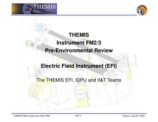
THEMIS Electric Field Instrument (EFI) • J. W. Bonnell • Space Sciences Laboratory • Univ. of Calif., Berkeley
EFI Block Diagram A High-Input Impedance, Low-Noise Voltmeter in Space sheath sensor preamp floating ground generation bias generation
Science Requirements • EFI-1: The EFI shall determine the 2D spin plane electric field at the times of onset at 8-10 Re (4.1.1.7, 4.1.1.9). • EFI-2: The EFI shall determine the dawn-dusk electric field at 18-30 Re (4.1.1.3). • The EFI shall measure the 3D wave electric field from 1-600 Hz at the times of onset at 8-10 Re (4.1.1.11). • The EFI shall measure the waves at frequencies up to the electron cyclotron frequency that may be responsible for electron acceleration in the radiation belt (radiation belt science).
Performance Requirements • EFI-5: The EFI shall measure the 2D spin plane DC E-field with a time resolution of 10 s (EFI-1, EFI-2). • EFI-6: The EFI shall measure the 3D AC E-field from 1 Hz to 4 kHz (EFI-3). • EFI-7: The EFI shall measure the Spacecraft Potential with a time resolution better than the spin rate (3 s; from ESA to compute moments). • EFI-8: The EFI FFT Spectra range shall be 16 Hz to 4 kHz, with df/f~25% (EFI-3). • EFI-9: The EFI shall measure DC-coupled signals of amplitude up to 300 mV/m with 16-bit resolution. • EFI-10: The EFI shall measure AC-coupled signals of amplitude up to 100 mV/m with 16-bit resolution. • EFI-11: The EFI noise level shall be below 10-4 (mV/m)/Hz1/2 [TBR]. • EFI-12: The EFI HF RMS (log power) measurement shall cover 100-500 kHz with a minimum time resolution of the spin rate (on-board triggers). • EFI-13: The EFI shall achieve an accuracy better than 10% or 1 mV/m in the SC XY E-field components during times of onset (EFI-1, EFI-2).
Performance Specification • EFI radial sensor baseline will be 40 m, tip-to-tip. • EFI axial sensor baseline will be ~10 m, tip-to-tip. • 16-bit resolution. • Spacecraft potential: +/- 60 V, 1.8 mV resolution, better than 46 uV/m resolution (allows ground reconstruction of E from spacecraft potential to better than 0.1 mV/m resolution). • DC-coupled E-field: +/- 300 mV/m, 9 uV/m resolution. • AC-coupled E-field: <= +/- 100 mV/m, 3 uV/m resolution.