Download
1 / 40
400 likes | 418 Vues
Explore the critical design review of the THEMIS ESA Plasma Instrument, measuring 3-D particle distributions and energy functions during substorms. Learn about the heritage, implementation, and efficient testing strategies used in the design process.

E N D
THEMIS • TIME HISTORY OF EVENTS AND MACROSCALE INTERACTIONS DURING SUBSTORMS • RESOLVING THE MYSTERY OF WHERE, WHEN AND HOW AURORAL ERUPTIONS START • THEMIS Mission Critical Design Review – ESA • June 14 – 18, 2004 • University of California, Berkeley
ESA Plasma Instrument Mission CDR Dr. C. W. Carlson and THEMIS ESA Team UC Berkeley SSL
Overview • ESA Plasma Instrument • Requirements & Specifications • Heritage • Design Overview • Block Diagram • Component Descriptions • Mechanical • Test and Calibration
Requirements and Specifications • Measurement • The ESA instrument measures 3-D electron and ion energy distribution functions over the Energy range 10 eV to 30 keV. Typical energy sweep has 16 or 32 energy samples • A full 4-pi distribution measurement is produced during each spin • Sweep rate of 32/spin gives dense sample of 3-D particle distributions • Raw measurements are compressed to selectable “reduced distributions” and moments • Implementation • Ion and electron “top-hat” electrostatic analyzers have 180 degree field of view • Field of view is divided into 8 electron and 16 ion elevation bins • Plasma analyzers have hardware programmed functions: sweep rate, sweep waveform, energy range, data collection rates. These functions are set by command. • Higher level data formatting and computed products are carried out in the ETC board. Energy sweep is exponential with programmable starting energy and step ratio
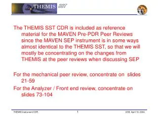
Heritage • ESA Instrument Design is based on FAST plasma instrument • Nearly identical measurement requirements • Well proven design – all 16 FAST ESA detectors remain fully functional after 7 years in orbit (Design requirement was 3 years in high radiation environment) • Flight hardware designs and calibration facilities can be used with minor changes • The only major electronics design change is to upgrade from the ACTEL 1020 gate arrays to the ACTEL RT54SX72S. This reduces the number of components required and makes the design consistent with other THEMIS instruments. • THEMIS instrument uses the FAST strategy of “dumb” sensors having hardware defined measurement modes, combined with a “smart” processor-based interface board that performs data formatting and higher level computations. The ETC board provides this intermediate processing for both the ESA and SST.
ESA Development Team • ESA Systems • Definition and Specifications: Charles Carlson • Mechanical: Bill Elliott, Paul Turin • Analog and Digital Systems: Charles Carlson, Mike Ludlam • IDPU Instrument Interface: Robert Abiad • Flight Software: Frank Harvey • Fabrication and Parts Management: Chris Scholz • Thermal: Chris Smith • MCP Testing: Mario Marckwordt, Jeff Hull • Calibration and Test Facilities: Mario Marckwordt • Ground Support Equipment: Jim Lewis • Spacecraft Integration & Test Requirements: Bill Elliott • ESA Support Functions • Probe Interfaces: Ellen Taylor • Reliability and Quality Assurance (R&QA): Ron Jackson • Parts Engineering: Jorg Fischer
MCP Pulse Amplifiers DigitalInterface & HV Sweep HV Supplies } Design Overview • THEMIS Uses FAST ESA Design • (1/2 of a FAST module) • Modular for efficient testing, assembly and repair • Entrance sealed and nitrogen purged • Outstanding operational performance • Specifications: • 180 degree elevation field of view with a minimum angular resolution of 22.5 degrees. • To resolve the solar wind the IESA will have a field of view with enhanced resolution of approximately 5.62 degrees.
THEMIS ESA • Simplified View of the new THEMIS ESA mechanical design illustrating design changes. • Changes from FAST • Ion Detector Anode pattern • Cover Release Mechanism (SMA Actuator) • Upgrade ACTEL Gate Arrays to RT54SX72S • HV Supplies repackaged in pairs • Higher density ACTELs on Preamp Board and Main Interface Board
Block Diagram • Electronics functional design is identical to FAST (with ACTEL upgrades) • Three circuit modules plug together for efficient assembly and test • MCP pulse amplifiers are Amptek A121 with programmable gain • All discrete logic, counters, and HV DAC drivers are Actel FPGAs • HV & LV supplies are mature designs built at UCB SSL
Analyzer/Anode/Preamp • Themis uses FAST module design • IESA/EESA Analyzers • Analyzer deflection plates • Aperture closer mechanism • UV rejection Cu-Black coating • Nitrogen purge system • Anode Boards • Mounts MCPs • HV Interface connectors • HV coupling capacitors • Preamp Board • AMPTEK A121 preamps • Actel logic arrays • Anode and Logic board interfaces FAST ESA module
MCP/Anode Board Assembly • Anode boards includes: • MCP Mounting Hardware • “Spring finger” clamp rings • HV electrode connections • Nitrogen purge plumbing • HV Interface • HV Plugs and wiring • HV filter capacitors • Bias resistor • Preamp Interface • Limit resistors & clamp diodes • Preamp interface connector • Materials • Polyimide / glass PCB • PEEK mounting rings • KAPTON spacers • Gold plated Be Cu springs Top Bottom 16 Anode 8 Anode
MCP Preamp/Accumulator • Preamp board includes: • 24 AMPTEK A121 hybrid preamps • ACTEL Gate array contains: • 24 x 14 bit accumulators • Command/Data Interface • Command interpreter • Test pulse generator • Preamp gain control DAC driver • Commandable selective anode blocking • MCP Anode board interface • Radiation “spot shielding” for preamps
HV Sweep & Digital Interface Modified FAST Sweep/Interface Board Themis board is about 30 % shorter length • HV Sweep/ Interface board includes: • Main data interface to ETC board and IDPU power board • HV fixed and sweep supply control • HV Sweep waveform generator (Amptek HV-601 high voltage optocouplers) • Housekeeping multiplexer • Plug-in interface to anodes and HV supplies
FAST HV Supply Assembly FAST HV Interface Board (mounts on back side of Sweep/Interface board) Themis board is about 30 % shorter length • HV Assembly board includes: • Four HV supplies with interface mother board (FAST example has 6 supplies) • Supplies are packaged as a pair of dual supplies. • HV supply assembly and Digital interface boards share structural mount plate • HV supplies have HV sockets that mate directly with HV plugs on HV sweep board and on anodes.
HV Supply and VMI Multiplier A single FAST HV Supply shown with a sample FAST HV multiplier module and the commercial replacement module from VMI (HM402N10). A total of 25 HV supplies on FAST have operated without incident for seven years. 2 Dual THEMIS HV Supplies • The VMI multiplier replaces the SSL fabricated component: • Huge saving of in-house technician work • VMI part has been tested for use on STEREO • The multiplier is physically and electrically compatible with existing FAST design • THEMIS Design has a pair of dual HV Supplies
ESA Instrument Power Supply • Low Voltage Converter • Direct Copy of FAST Design • Regulation and Current Limiting of Primary 28 Volt Input is Provided by IDPU Power Control Board • Reference Voltages Generated by Secondary Regulators • Power Converter Provides Isolated Grounding for ESA
Test and Calibration • UCB SSL has automated calibration facilities (FAST, WIND heritage) that will be used for THEMIS ESA calibrations • Facility uses cryogenic pumped vacuum chambers with computer controlled ion and electron guns and 3-axis manipulators • New Ion Gun Facility will be used for both ESA and SST calibrations (See SST Calibration Presentation) • All six ESA units (5 flight/ 1 spare) use identical calibration procedures adapted from FAST • Full environmental testing (Thermal / Vacuum, EMC, Vibration) 3 Axis Manipulator Calibration Chamber
ESA GSE Block Diagram To lab network, optional external monitoring and commanding Vacuum chamber CMD Gate 6U GSE Interface Board + Nios embedded processor Electron and ion guns CMD Clock Ethernet router CMD Data Ethernet ESA TM Clock Manipulator TM Data Analog HSK PWR Ethernet GSE software: based on Mike Hashii’s STEREO GSE tools, FAST calibration S/W 3-axis servo amplifier PCI motion controller Digital Multimeter Bench LVPS GSE workstation HVPS GPIB via USB
ESA GSE Software • Capabilities: • Scripted or interactive entry of CDI, GPIB, and manipulator commands • Simulates ETC board to command ESA and acquire telemetry • Real-time display of counter histograms, raw hex telemetry dumps, analog housekeeping values, manipulator status • Can act as TCP/IP server for remote monitoring or controlling via MATLAB, IDL, or LabWindows/CVI code • Telemetry and log messages archived to disk for later examination and processing • Device control • GPIB programmable LV and HV power supplies, digital multimeter • Internal PCI motion controller, external servo amp and motor drive • TCP/IP interface to 6U VME GSE Interface Board for sending CDI commands, acquiring telemetry and analog housekeeping values
Circuit Board Mounting Interface Bracket Interface Circuit Board High Voltage Circuit Boards Mother Board
ESA Exploded (Close-up) Cover Assembly Aperture Ring Hemisphere Assembly Detector Base Anode Assembly Radiation Shield
Typical ESA Anode Assembly (Exploded) Anode Plenum Ring Plug Regulator Spacer, OD Spacer, ID Dowel Pin, PEEK Micro Channel Plate (MCP) Spring Plate Clamp Spring, Inside Clamp Spring, Outside Spacer, OD Spacer, ID Grid, MCP Clamp Ring, OD Clamp Ring, ID
Typical Hemisphere Cross-Section • Design Features: • Interior Surface of Outer Hemisphere is Serrated & Interior Surfaces of Both Hemispheres are Ebanol (Copper Black) Coated for UV Rejection • Exit Grid Isolates the Analyzer Optics from MCP Bias Voltages • Both Hemispheres Mounted to Single Structural Plate to Ensure Good Alignment
Typical ESA HEMISPHERE Assembly Outer Hemisphere O-Ring Inner Hemisphere Dome Tab Dome Mount Grid, Hemisphere Spider Plate
Hemisphere Cover Assembly Hemisphere Cover Cover Gasket Diaphragm Spring Spring Clamp Gasket Clamp
Cover Release in Cocked (Closed) Position Release Plate Compression Spring Slider, IESA Slider, EESA Release Spring Roller Pin Release Rod Roller Shim Nut Plate, Spring Nut Plate, Slider Chock, Spring Bushing, Linkage Tube, Linkage Link, EESA Link, IESA Bearing Cap Spring Mandrel Ball Bearing Linkage Spacer Nut Plate, Actuator Bushing, Actuator Link Bearing, Linkage Washer, Actuator Link SMA Actuator Tee Bone Link, Actuator Switch Actuator, Switch Nut Plate Spring Block Washer Plate
Release Plate Mechanism Cocking • Mechanism is cocked externally • It is reset-able • A “Red Tag” cocking nut may be screwed on the end of the cocking pin to prevent premature actuation of the mechanism. • When cocked, there is an external visual indication: the tip of the cocking pin protrudes slightly from the cocking barrel.
SMA Actuator & Mechanism Test Results • Extensive Testing • Vibration Testing • 10-27-03 Successful 4 minute GEVS test of standard NanoMuscle • 12-8-03 Successful 4 minute GEVS test of SSL redesigned SMA Actuator (based on NanoMuscle components) • 2-23-04 Successful 4 minute GEVS test of SMA Actuator and Release Plate Assembly (Did Not Trip Open, Did Open On Command After Vibe Test) • Combined ESA + IDPU 6-9-04 • Final Test in Thermo-Vacuum to be done on all Flight Hardware • Cycle Testing • 2-15-04 Successful completion of three million cycle test of previously Vibration Tested SMA Actuator. • Test Each Flight Actuator at instrument operating temps • for 1000 Cycles • We will be testing Mechanism in July +/- 10 deg operational limits
SMA Actuator Margin Analysis • SMA Actuator rated at 125 g pull force • Force required to pull roller off center (including spring) adjusted to be 35-40 g • Force ratio >3 • In addition, we have an additional, redundant SMA Actuator (Pictured Right)
Nitrogen Purge & HV Enable Plug • NITROGEN PURGE • A Nitrogen Line is connected to the ESA Purge Fitting preflight to purge the Interior of the Analyzer. • The Nitrogen is supplied at 5 psig and is regulated and filtered in-line at each Anode to supply 1 liter/hour. • Purge is accessible on assembled spacecraft. • HV ENABLE PLUG • Plug is accessible on assembled spacecraft. HV ENABLEPLUG
ESA S/C INTERFACE • Interface to Spacecraft • ESA Mounts To IDPU • ESA + IDPU Will Be Installed As a Single Unit • ESA Extends Through Corner Panel With 0.100” Clearance all around • “Red Tag” Purge Gas Connection and Dust Shield • “Green Tag” Purge Gas Cover & HV Enable Plug COCKING PIN PURGE CONNECTOR HV ENABLE PLUG