Download
1 / 1
20 likes | 226 Vues
Design of B a Passive Microfluidic Mixer for BioMEMS Application Fei Mi , Shuhan Kan , Advisor: Prof. Xingguo Xiong Department of Biomedical Engineering, University of Bridgeport, Bridgeport, CT 06604. Results and Discussions. Abstract.

E N D
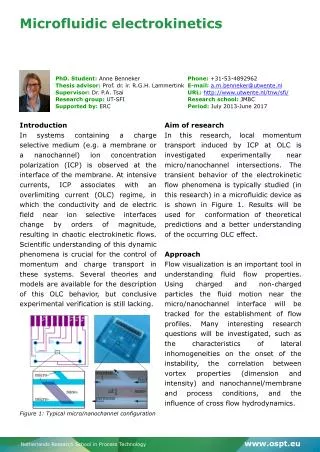
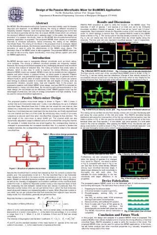
Design of Ba Passive Microfluidic Mixer for BioMEMS Application Fei Mi, Shuhan Kan, Advisor: Prof. Xingguo Xiong Department of Biomedical Engineering, University of Bridgeport, Bridgeport, CT 06604 Results and Discussions Abstract ANSYS FEM simulation is used to verify the function of the MEMS mixer. The velocities of both of species 1 and species 2 at inlets are set to be 1000μm/s (boundary condition). Density of species 1 and 2 are set as 1g/cm3 and 1.5 g/cm3 respectively. Hand calculation shows the Reynolds number of the microfluid flows are under 10, which belongs to laminar flow. The meshed ANSYS model of the MEMS mixer is shown in Fig. 2. The contour plot of the flow density is shown in Fig. 3. From Fig. 3, we can clearly see how both microfluid flows are mixed rapidly along the channels. The blue and red color represent microfluid species 1 and 2 respectively. Once both fluids are thoroughly mixed, its color becomes uniform yellow. Bio-MEMS (Bio-Microelectromechanical Systems) have been widely used for disease diagnosis and treatment. In bio-MEMS devices, the mixing of different microfluid is frequently needed. However, such mixing has been very challenging due to the fact that microfluid is generally laminar flow. As a result, MEMS mixers which can enhance the mixing of different microfluid are in pressing need. In this poster, the design and simulation of a passive microfluidic mixer for Bio-MEMS (bio-microelectromechanical systems) application is proposed. The proposed MEMS mixer utilizes re-convergent channels to introduce turbulence, hence enhancing the mixing of two different microfluidic flows. The mixing of microfluid in the proposed mixer is analyzed. Based on the theoretical analysis, the dimension parameters of the mixer is decided. ANSYS simulation is used to verify the effectiveness of the MEMS mixer device. The fabrication flow of the MEMS mixer is also suggested. The proposed MEMS mixer can be used for lab-on-a-chip, digital microfluidics, micro-drug delivery system and other bio-MEMS applications. Introduction Bio-MEMS devices need to manipulate different microfluids, such as blood, saliva, urine samples. The mixing of different microfluid samples are frequently needed. However, the mixing of microfluid samples is very challenging because most microfluid is laminar flow instead of turbulent flow. The mixing of laminar flow solely relies on diffusion, which is very slow. In order to improve the mixing efficiency, specially designed MEMS mixers are needed. MEMS mixers can be divided into two categories: passive and active mixers. In passive mixers, no active power is required. Passive micro-mixers just use geometrical shape or fluid characteristics, to generate and mix different fluids to get the effect of chaotic advection. Active micro-mixers use exterior input energy to produce pulses to increase the rate and degree of mixing, such as piezoelectric vibration, acoustic wave, heat and magnetic field. In this project, we proposed a passive multi-folded MEMS mixer design, and use ANSYS to simulate its effectiveness in mixing microfluid flows. By introducing split-and-recombination in the mixer design, the microfluids can be effectively mixed. MEMS passive mixer has the advantages of small size, low cost, no energy consumption and high reliability. It can be used for various biomedical applications. Fig. 2 Meshed ANSYS model of mixer Fig. 3 Contour plot of density distribution The flow velocity vector plot of the microfluid along MEMS mixer is shown in Fig. 3. From Fig. 3, we can clearly see that turbulence (change of flow velocity direction) is successfully induced at each turn corner along the mixer, which is very helpful for the mixing of laminar flow. The local view of the velocity turbulences are shown in Fig. 5. Passive Micro-mixer Design The proposed passive micro-mixier design is shown in Figure 1. With 3 inlets (1 vertical inlet and 2 horizontal inlets) and 1 outlet, it can effectively mix up to 3 different microfluid flows. Microfluid flows from 3 inlets are first mixed into one channel, then divided into 2 branches and then further divided into four sub-branches. After that, the flows from 4 sub-branches are mixed back into two branches, and finally rejoined back into one channel and flow out of the outlet. By introducing many rounds of turn-overs, turbulence is induced each time when microfluid flow changes its flow direction. The total length of the micro-mixer is about 20480 µm. The channel width are also dynamically adjusted to adapt to different amount of microfluid flow along the channel. For example, if multiple branches are joined together, the corresponding channel is enlarged to accommodate the increased microfluid flow. If a channel is divided into multiple branches, the corresponding branches are narrowed to adapt to the reduced microfluid flow. Fig. 4 ANSYS fluid velocity vector plot Fig. 5 Local view of induced tubulence The mixing can be verified not only from density contour plot, but also the density path plot along the cross section of the inlet and outlet. The ANSYS simulated density distribution plot along the cross section of the first top vertical channel section near the inlets is shown in Fig. 6. We can see the microfluid is not well mixed yet at this time, because there are more species 1 in the middle, and more species 2 in both sides close to the channel sidewalls. After passing the MEMS mixer, the density path plot along cross section of outlet is shown in Fig. 7. It shows the microfluids (species 1 and 2) are now thoroughly mixed, and a uniform density distribution is achieved. Table 1. Micro-mixer design parameters Fig. 6 Density distribution near inlet Fig. 7 Density distribution at outlet Furthermore, we also simulated the case when the density of species 2 is changed from 1g/cm3 to 35g/cm3, the result is shown in Fig. 8. Compared with result in Fig. 3, we can see that as the initial density different among input microfluid becomes larger, it takes longer distance for both microfluids to thoroughly mix with each other. This indicates it’s more challenging to mix two microfluids with larger difference in its properties. Figure 1. Structure of passive micro-mixer Assume the microfluid flow in vertical inlet (labeled as fluid A) contains a solution like protein, and the concentration is set to 1. For the microfluid flow in two horizontal inlets (labeled as fluid B) is the same and its concentrations is set to be 0 (i.e. pure water). Based on microfluid dynamics analysis, we can estimate the mixing efficiency as well as the intensity of segregation and variation coefficient of the microfluid flows inside the mixer. In additional, Reynolds number is also a very important factor of fluid flow measuring the ratio between inertial forces and viscous in particular flow. For Reynolds number below 2100, we can get laminar flow in which the fluid molecules travel along well-ordered non-intersecting paths or layers. When Reynolds number is over 4000, we can get turbulent flow that fluid molecules from adjacent layer become totally mixed. For microfluidics, generally we get laminar flow. Fig. 8 Density plot (ρ2=35g/cm3) Device Fabrication The proposed passive MEMS mixer is to be fabricated with Si bulk-micromachining and bonding techniques. The fabrication flow is shown in Fig. 9. • Preparing for the silicone wafer; • Si thermal oxidation to grow 0.2µm SiO2, • Photolithography, etching SiO2 to open windows, • Use SiO2 as etching mask, KOH anisotropic etching to etch down microchannels, • Remove all SiO2 with buffered HF solution, • Bond Si wafer with Pyrex #7740 glass by Si-glass anodic bonding technique, the microchannels are sealed with glass top cover. The MEMS miccromixer device fabrication is completed. Reynolds Number is calculated as: The equation of Mixing Efficiency: where Ci is the mole percentage of the No. i dot in a certain area, n is the number of style points in a certain cross section, is the ideal mole percentage, Ci is a number in range from 0 to 1. When Ci is 0.5, it indicates A fluid and B fluid are mixed completely. Fig. 9 Fabrication flow of mixer Conclusion and Future Work In this project, the design and analysis of a passive MEMS mixer is proposed. The passive MEMS mixer utilizes multiple turns to improve the mixing efficiency of laminar microfluid flows. ANSYS simulation is used to verify the function of the mixer. The proposed MEMS mixer can be used for various bio-MEMS applications. In the future, we will further analyze how other microfluid properties (e.g. viscosity, temperature) affect the mixing result of the mixer. The Intensity of Segregation and Variation Coefficient: and are the standard deviation of the mass fraction of species at the inlet and outlet of micromixer, is the mass fraction of species at the inlet.


![An LTE Transmitter Using a Class-A/B Power Mixer[1]](https://cdn1.slideserve.com/2385860/an-lte-transmitter-using-a-class-a-b-power-mixer-1-dt.jpg)