CSC: 345 Computer Architecture
CSC: 345 Computer Architecture. Jane Huang Lecture 5 Memory Organization Error Correction. Review of cache. Stallings Question 4.2 For the hex main memory addresses 111111,666666,BBBBBB show the following information in hex form:


CSC: 345 Computer Architecture
E N D
Presentation Transcript
CSC: 345 Computer Architecture Jane Huang Lecture 5 Memory Organization Error Correction
Review of cache • Stallings Question 4.2For the hex main memory addresses 111111,666666,BBBBBB show the following information in hex form: • Direct mapped cache: 16Mbyte main memory, with FFFC words of 32 bits each. 16Kword cache with 3FFF words of 32 bits each: • Show Tag, Line, and Word values for these addresses. • Associative cache:
Direct mapped cache: 16Mbyte main memory, with FFFC words of 32 bits each. 16Kword cache with 3FFF words of 32 bits each: • Show Tag, Line, and Word values for these addresses. • Specify the following values for hex addresses 111111, 666666, BBBBBB • Word • Line • Tag
Associative Memory • Address length • Number of addressable units • Block size • Number of blocks in main memory • Number of lines in cache • Size of tag.
Two-way set associative cache • Address length • Number of addressable units • Block size • Number of blocks in main memory • Number of lines in set • Number of sets • Number of lines in cache • Size of tag.
Semiconductor Main Memory • Basic element – memory cell • Exhibit 2 stable states used to represent 0 and 1 • Can be written into (at least once) • Can be read to sense state • Random Access Memory • Read and write easily by use of electrical signals • Volatile – must be provided with a constant electrical supply or else data will be lost. (only good for temporary storage). • DRAM (Dynamic) and SRAM (Static)
Dynamic RAM (DRAM) • DRAM made from cells that store data as charge on capacitors. (Charge = 1, no charge = 0) • Capacitors have a tendency to discharge. • DRAMS need periodic refreshing to maintain data storage. Static RAM (SRAM) • SRAM is a digital device. • Binary values stored using traditional flip-flop logic gates. • SRAM holds value as long as power is supplied. SRAM vs. DRAM • Both volatile • DRAM is simpler, smaller, denser, less expensive – but needs refresh circuitry. (Only worthwhile for larger memories – main memory). • SRAM is faster, more expensive – therefore usually used for smaller cache memories.
ROM • Read-only memory • Contains a permanent pattern of bits, therefore no power source needed to maintain bit values. • Created like any other integrated chip. • Useful for microprogramming, system programs, function tables etc. • Problems: • Large fixed cost incurred for 1 or 1000s of chips. • No room for error. • Programmable ROM • If only a small number of ROMs of one memory content are needed, a good alternative is programmable ROM (PROM) • PROM can only be written once, but the writing process is performed electronically and need not be done at the time of original chip fabrication. • Provides flexibility and convenience. • Read mostly memory • EPROM (Erasable programmable read-only memory – erases everything) • EEPROM (Electrically erasable programmable read-only memory – byte level) • Flash Memory (Uses electrical technology to flash erase one section)
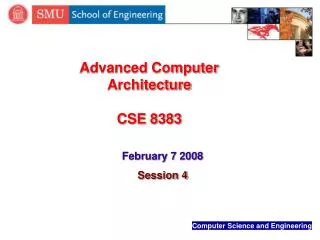
Chip “Art Gallery” Chip designers often ‘secretly’ add artwork to the chips they design. Where is Waldo? “We caught this silicon version of Waldo (that is about 30 microns in size) hiding among caches, buses, and registers while searching through many thousands of square microns of complex circuitry with a high-power optical microscope. Waldo is the first Silicon Creature that we discovered, and this led to an exhaustive search for more creatures and construction of the Silicon Zoo gallery. “ http://www.wired.com/news/print/0,1294,17028,00.html
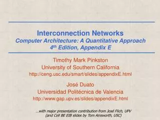
Chip “Art Gallery” Daffy Duck “As we see it, the engineers that designed this wireframe version of Daffy Duck must have had a very interesting sense of humor. We found it deeply embedded within the circuitry of a RISC microprocessor, about 1500 microns away from a similar-style rendition of Waldo. Daffy is about 50 microns in size, making it necessary to use a high-power (40X to 60X) microscope objective to photograph the wireframe character.” http://www.wired.com/news/print/0,1294,17028,00.html
0000 0001 0010 0011 0100 0101 0110 0111 1000 1001 1010 1011 1100 1101 1110 1111 Four-input sixteenoutputdecoder X1 X2 X3 X4 Z1 Z2 Z3 Z4 64 bit ROM
Use of a ROM to B2 B1 B0 G2 G1 G0 An example of ROM implement a 0 0 0 0 0 0 conversion from 0 0 1 0 0 1 Binary to Gray Code 0 1 0 0 1 1 (A 24 bit Rom 0 1 1 0 1 0 • ROM only performs the read operation. • A given input always produces the same output. • Therefore a ROM is just a combinational circuit. • Also can be viewed as a memory of n words * b bits, where 2n = the number of inputs, and b = the number of outputs. consisting of 8 1 0 0 1 1 0 1 0 1 1 1 1 words of 3 bits each) 1 1 0 1 0 1 1 1 1 1 0 0 000 001 B2 010 Three Input 011 Eight Output B1 100 Decoder B0 101 110 111 G2 G1 G0
Chip Logic • Trade offs in terms of speed, capacity, and cost. • Physical arrangement of cells matches logical arrangement.Memory array organized into W words of B bits each.Example: 16-Mbit chip 1 M 16-bit words. • One-bit-per chip organization. Data is read/written one bit at a time. 16-MBit DRAM
Typical 16 Megabit DRAM (4M X 4) • 19 bit address multiplexed into the Chip • Select an entire row using 11 most significant bits. • Select a column using 11 least significant bits. • Refresh circuitry (DRAM)
MAR MBR 512 1 Words by of 512 Decode 1 512 Bits Chip # 1 2 9 Decode 1 of 3 512 Bit-Sense 4 5 9 6 7 512 8 Words by Decode 1 of 512 512 Bits Chip # 7 Decode 1 of 512 Bit-Sense 512 Words by of 512 Decode 1 512 Bits Chip # 8 Decode 1 of 512 Bit-sense 256-Kbyte Memory Organization • In this example a RAM chip contains 1 bit per word. • For 256K 8-bit words – we need 8 chips. • Row address simultaneously sent to all 8 chips. • Followed by column address simultaneously sent to all 8 chips.
Group Exercise • Design a 512K 4 bit memory using 256X256 chips. • Show how the address would be used to access data.
Error Correction • A semiconductor memory system is subject to errors. • Hard failures – permanent physical defectsEnvironmental abuse, manufacturing defects, wear. • Soft error Power supply problems, alpha particles. • Need logic for detecting and correcting errors. • Basic technique • Prior to storing data a code is generated from the bits in the word. • Code stored alongside the word in memory. • Code used to identify and correct errors. • When the word is fetched a new code is generated and compared to the stored code. • No error (normal case) • Correctable error is detected and corrected. • Non-fixable error is detected and reported.
1 1 1 0 1 1 1 0 1 0 0 Assign data bits to the inner compartments. Fill the remaining compartments with parity bits. The total number of bits in a circle must equal 1. For example: The data bits in A = 1+1+1 = 3. This is odd – therefore add an additional Hamming Code A B A B C C
A B 1 1 1 0 C Hamming Code A B A B 1 1 1 0 1 0 1 1 0 1 0 0 0 0 0 C C If a bit gets erroneously changed, the parity bits in that circle will no longer add up to 1. Errors are found in A and C – and the shared bit in A and C is in error and can be fixed.
Single Bit Errors in 8-bit words • 8 data bits • The code needs to represent the bit position of the error. For example, if bit # 2 were in error (10011001 10011011) we would like the syndrome word to output a value of 2 (0010). If no errors occurred the code should output 0 (0000) • Therefore code length (K) must be greater or equal to Log2W + 1, where W = word length. ie for 8 bits, it must be big enough to represent numbers 0 – 8, therefore 4 bits are needed. • No errors – code = 0. • One error bit – error occurred in one of the check bits. No action. • More than one bit set to ‘1’ – the numerical value of the syndrome indicates the position of the data bit in error.
Single Bit Errors in 8-bit words • Data and check bits arranged into a 12-bit word. • Bit positions numbered from 1 to 12. • Bit positions representing position numbers that are powers of 2 are designated as check bits. • Check bits calculated as follows: • Data and check bits arranged into a 12 bit syndrome word: 8 data bits 4 check bits
Calculating check bits C1 = D1 D2 D4 D5 D7 Each check bit works on every data bit who shares the same bit position
Example • Input word: 00111001 Databit D1 in rightmost position • Calculate check bits: • C1 = 1 0 1 1 0 = 1 • C2 = 1 0 1 1 0 = 1 • C3 = 0 0 1 0 = 1 • C4 = 1 1 0 0 = 0Stored word = 001101001111 • If data bit 3 sustains an error (001101101111) • C1 = 1 0 1 1 0 = 1 • C2 = 1 1 1 1 0 = 1 • C3 = 0 1 1 0 = 1 • C4 = 1 1 0 0 = 0 • Calculate syndrome word:0110 = bit position 6. • D3 resides in bit position 6.
c. a. b. 1 1 0 1 0 1 0 0 1 1 1 0 1 0 1 0 0 0 1 1 Two errors are introduced Fill in data bits. Calculate check bits. f. d. e. 1 1 1 1 1 1 0 0 0 0 0 0 1 1 1 0 1 1 0 0 0 1 1 1 The double error is detected! The extra bit checks for even parity. SEC identifies the wrong bit Double Error Detecting • Previous example is Single-Error-Correcting code. • Semiconductor memory is usually equipped with SEC-DED (Single-error-correcting, double-error-detecting code. SEC-DED requires an extra bit.
Performance • Access Time (latency) • Random Access = time taken to perform a read or write. • Non-random access memory = time to position read-write mechanism at desired location. • Memory Cycle Time • Access time + additional time required before a second access can commence. • Affected by behavior of the system bus not the processor. • Transfer Rate • Rate at which data can be transferred into or out of a memory unit. • For random access memory = 1/(cycle time). • Non random-access memoryTN = TA + ( N / R)TN = Average time to read or write N bits • TA = Average access time • N = Number of bits • R = Transfer rate, in bits per second (bps)
Magnetic Disks • Tracks: Hard Disk platters arrange data into concentric circles, rather than one large spiral, as some other mediums use. Each circle is called a Track. • Sectors: The smallest addressable unit on a Track. Sectors are normally 512 bytes in size, and there can be hundreds of sectors per track, depending on location.(Constant bit density – more sectors on outer tracts) • Heads: The devices used to write and read data on each platter. • Cylinders: Platters on a hard disk are stacked up, and so are the heads. Concentric circles from each parallel platter form a cylinder. (Think Stargate!) http://www.pcguide.com/ref/hdd/geom/tracksDifference-c.html
Reading and Writing • SEEK: Disk controller sends a command to move the arm over the proper track. = Seek Time. • Seek time • Minimum / Maximum • Average? Sum of all possible seeks divided by the number of possible seeks. What is wrong with this??? • Rotation latency (delay) • Time for requested sector to rotate under the head.Average = halfway around disk. (0.5) • If a disk rotates at 10,000 RPMAvg Rotation time = 0.5 / 10,000 RPM • = 0.5 / (10,000/60) RPS • = 0.0030 sec = 3.0 ms. • Transfer time • Time it takes to transfer a block of bits. (typically a sector)Function of block size, disk size, rotation speed, recording density, etc.
Example • What is the average time to read or write a 512-byte sector for a disk? The advertised average seek time is 5ms, the transfer rate is 40MB/sec, it rotates at 10,000 RPM, and the controller overhead is 0.1ms. Assume the disk is idle so that there is no queueing delay. In addition, calculate the time assuming the advertised seek time is three times longer than the measured seek time. • Answer: • Average disk access = average seek time + average rotational delay + transfer time + controller overhead. • = 5ms + 0.5 + 0.5KB + 0.1ms • 10,000 RPM 40 MB/sec • = 1.67ms + 3.0ms + 0.013ms + 0.1ms = 4.783ms
RAID • Redundant Array of Independent Disks • Disk storage designers recognized that if access times etc can only be improved to a certain extent – additional performance can be gained by introducing multiple disks. • Introduced possibility of more errors. • RAID: Improve access time + improve reliability. • Set of physical disk drives viewed as the Operating system as a single logical drive. • Data are distributed across the drives of an array. • Redundant disk capacity is used to store parity information – guaranteeing data recoverability in case of a disk failure. Picture from:http://mst2.lcc.whecn.edu/byeager/whitepapers/raid.pdf
RAID Level 0 • Not a true member of the RAID family - does not include redundancy to improve performance. • User and system data distributed across all disks in the array in strips. • Imagine a large logical disk containing ALL data. This is divided into strips that are mapped ‘round robin’ to the strips in the array. • + If two different I/O requests are pending for two different blocks of data – then there is a good chance that the data will be on different disks and can be serviced in parallel. • + If a single I/O request is for multiple logically continuous strips – up to n strips can be handled in parallel.
RAID Level 1 • Redundancy achieved through duplicating all data. • Each logic strip is mapped to two physical disks. • + Read request can be serviced from either available disk. • Write request requires both disks to be updated – but this can be done in parallel. (Slower write dictates overall speed). • + Recover from failure is simple! Picture from: http://mst2.lcc.whecn.edu/byeager/whitepapers/raid.pdf
RAID Level 2 • Utilizes parallel access techniques - All disks participate in the execution of every I/O request. • Spindles of individual drives are synchronized so that each disk head is in the same position on each disk at any given time. • Data striping – very small strips (single byte or word). • Error correcting code calculated across corresponding bits on each disk, and the code bits are stored in corresponding bit positions on multiple parity disks. • For Hamming Code – number of parity disks is proportionate to the log of the number of data disks.Array control can detect and fix single bit errors. • For write – all disks must be accessed. • Good choice – only for an environment in which many errors occur – therefore not used much.
RAID Level 3 • Similar to RAID 2 – parallel access with data distributed in small strips. • Only requires a single redundant disk because it uses a single parity bit for the set of individual bits in the same position. • If drives X0-X3 contain data, and X4 contains parity bits. • X4(i) = X3(i) X2(i) X1(i) X0(i) • Redundancy – in the case of disk failure, the data can be reconstructed.If drive X1 fails – it can be reconstructed as: • X1(i) = X4(i) X3(i) X2(i) X0(i) • Performance – can achieve high transfer rates, but only one I/O request can be executed at one time. (Better for large data transfers in non transaction-oriented environments).
RAID Level 4 • Each disk operates independently - Separate I/O requests satisfied in parallel. • Suitable for applications with high I/O request rates and NOT well suited for those requiring high data transfer rates. • Data striping. (Strips are larger than in lower RAIDs). • Bit-by-bit parity calculated across corresponding strips on each data disk, and stored in corresponding strip on the parity disk. • Performance – write penalty when I/O request is small size. Write must update user data + corresponding parity bits. • X4(i) = X3(i) X2(i) X1(i) X0(i) • If X1(i) is changed to X1’(i) X4(i) = X3(i) X2(i) X1’(i) X0(i) = X4(i) X1(i) X1’(i)
RAID Level 5 • Same as RAID 4 – but parity strips distributed across all disks. • Typical allocation uses round-robin. • For an n-disk array, the parity strip is on a different disk for the first n strips. • Avoid potential bottleneck found in RAID 4.
RAID Level 6 • Two different parity calculations carried out and stored in separate blocks on different disks. • Example: XOR and a second independent data check algorithm. • No. of disks required = N + 2 (where N = number of disks required for data). • Provides HIGH data reliability. • Incurs substantial write penalty as each write affects two parity blocks.
Homework • Stallings 5.3Design a 16-bit memory of total capacity 8192 bits using SRAM chips of size 64X1 bit. Give the array configuration of the chips on the memory board showing all required input and output signals for assigning this memory to the lowest address space. The design should allow for both byte and 16-bit word accesses. • Stallings 5.5Suppose an 8-bit data word stored in memory is 11000010. Using the Hamming algorithm, determine what check bits would be stored in memory with the data word. Show how you got your answer. • Stallings 5.6For the 8-bit word 00111001, the check bits stored with it would be 0111. Suppose when the word is read from memory, the check bits are calculated to be 1101. What is the data word that was read from memory? • Stallings 6.3 (Question on RAID) • What is the average time to read or write a 512-byte sector for a disk? The advertised average seek time is 4ms, the transfer rate is 35MB/sec, it rotates at 8,000 RPM, and the controller overhead is 0.15ms. Assume the disk is idle so that there is no queueing delay.
Challenge Question • Stallings 5.3Design a 16-bit memory of total capacity 8192 bits using SRAM chips of size 64X1 bit. Give the array configuration of the chips on the memory board showing all required input and output signals for assigning this memory to the lowest address space. The design should allow for both byte and 16-bit word accesses. • Stallings 5.5Suppose an 8-bit data word stored in memory is 11000010. Using the Hamming algorithm, determine what check bits would be stored in memory with the data word. Show how you got your answer. • Stallings 5.6For the 8-bit word 00111001, the check bits stored with it would be 0111. Suppose when the word is read from memory, the check bits are calculated to be 1101. What is the data word that was read from memory? • Stallings 6.3 (Question on RAID) • What is the average time to read or write a 512-byte sector for a disk? The advertised average seek time is 4ms, the transfer rate is 35MB/sec, it rotates at 8,000 RPM, and the controller overhead is 0.15ms. Assume the disk is idle so that there is no queueing delay. • CHALLENGE QUESTION – See handout.