SHIP STRUCTURES
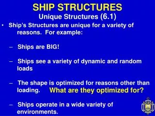
Unique Structures (6.1). SHIP STRUCTURES. Ship’s Structures are unique for a variety of reasons. For example: Ships are BIG! Ships see a variety of dynamic and random loads The shape is optimized for reasons other than loading.

SHIP STRUCTURES
E N D
Presentation Transcript
Unique Structures (6.1) SHIP STRUCTURES • Ship’s Structures are unique for a variety of reasons. For example: • Ships are BIG! • Ships see a variety of dynamic and random loads • The shape is optimized for reasons other than loading. • Ships operate in a wide variety of environments. What are they optimized for?
Ship Structural Loads (6.2) SHIP STRUCTURES • Up until now we have used Resultant (single point) Forces through “G” (s) and “B” (FB) Stern Bow
Ship Structural Loads (6.2) SHIP STRUCTURES • Buoyancy is actually a distributed force. (LT/ft) • Often it is uniformly distributed. The distribution follow the Curve of Areas.
Ship Structural Loads (6.2) SHIP STRUCTURES • Similarly, weight is a distributed force. • But it is rarely uniformly distributed. Many of the weights, such as the engines, are concentrated (point loads).
Ship Structural Loads (6.2) SHIP STRUCTURES • Nonuniform distributions produce shear planes at areas of unequal loading. • Overall force distributions are Load Diagrams
Ship Structural Loads (6.2) SHIP STRUCTURES For simplicity, we often model ships as simple beams. • Longitudinal Bending Moments are the principle load of concern for ships >100 ft.
Ship Structural Loads (6.2) SHIP STRUCTURES • If the beam sags, the top fibers are in compression and the bottom fibers are in tension.
Ship Structural Loads (6.2) SHIP STRUCTURES • A ship has similar bending moments, but the buoyancy and many loads are distributed over the entire hull instead of just one point. • The upward force is buoyancy and the downward forces are weights. • Most weight and buoyancy is concentrated in the middle of a ship, where the volume is greatest.
Ship Structural Loads (6.2) SHIP STRUCTURES • Buoyant force is greater at wave crests. • If the wave crest is at the bow and stern, the vessel is said to be sagging. The net effect is that the middle has less support.
Ship Structural Loads (6.2) SHIP STRUCTURES • If sagging loads get too large...
Ship Structural Loads (6.2) SHIP STRUCTURES • Hogging - Buoyancy Support in the Middle
Ship Structural Loads (6.2) SHIP STRUCTURES • Sagging - buoyancy support at the ends
Ship Structural Loads (6.2) SHIP STRUCTURES • The location where the beam remains its original length is called the neutral axis and marks the transition between tension and compression in a section. • The neutral axis is located at the geometric centroid of the cross section.
Ship Structural Loads (6.2) SHIP STRUCTURES • The maximum bending moment and simple beam theory enables us to determine the bending stress anywhere in the beam. The expression for bending stress is: • = My • I • where, • = bending stress in tons per ft2 • M = bending moment in ft-ton • I = second moment of area of structural cross section in ft4 • y = distance of any point from the neutral axis in ft
Ship Structural Loads (6.2) SHIP STRUCTURES • The bending stress at the neutral axis is zero.
Ship Structure (6.3) SHIP STRUCTURES • A ship structure usually consists of a network of frames and plates. • Frames consist of large members running both longitudinally and transversely. Think “picture frame.” • Plating is attached to the frame providing transverse and longitudinal strength. Think “dinner plate.”
Ship Structure (6.3) SHIP STRUCTURES
Ship Structure (6.3) SHIP STRUCTURES • Keel: Longitudinal center plane girder along ship bottom “Backbone”. • Plating: Thin skin which resists the hydrostatic pressure. • Frame: Transverse member from keel to deck. • Floor: Deep frames from keel to turn of the bilge.
Ship Structure (6.3) SHIP STRUCTURES • Longitudinals: Parallel to keel on ship bottom, provide longitudinal strength. • Stringers: Parallel to keel on sides of ship, also provide longitudinal strength
Ship Structure (6.3) SHIP STRUCTURES • Transverse Framing • Combats hydrostatic loads • Consists of closely spaced continuous frames with widely spaced longitudinals. • Best for short ships (lengths less than typical ocean waves: ~ 300ft) and submarines. • Thick side plating is required. • Longitudinal strength is relatively low.
Ship Structure (6.3) SHIP STRUCTURES frame plate DDG-51 DC Mat’l and Structure
Ship Structure (6.3) SHIP STRUCTURES • Longitudinal Framing • Consists of closely spaced longitudinals and widely spaced web frames. • Longitudinal framing resists longitudinal bending stresses. • Side plating is thin, primarily designed to keep the water out.
Ship Structure (6.3) SHIP STRUCTURES • Modern Naval vessels typically use a “Combination Framing System” • Typical combination framing network might consist of longitudinals and stringers with shallow web frames. • Every third or fourth frame would be a deep web frame. • Optimizes the structural arrangement for expected loading, minimize weight and cost.
Ship Structure (6.3) SHIP STRUCTURES
Ship Structure (6.3) SHIP STRUCTURES • Double Bottoms • Double bottoms are two watertight bottoms with a void (air) space in between. • They are strong and can withstand the upward pressure of the sea in addition to the bending stresses. • Provide a space for storing fuel oil, fresh water (not potable), and salt water ballast. • Withstand U/W damage better, but rust easier.
Modes of Structural Failure (6.4) SHIP STRUCTURES • The five basic modes of failure are: • Tensile or compressive yield (often from bending) • Compressive Buckling/Instability • Fatigue • Brittle Fracture • Creep
Modes of Structural Failure (6.4) SHIP STRUCTURES • Tensile or Compressive Yield • Plastic deformation due to applied > yield. • Failure criteria for many structures is that no stress shall exceed yield. • Factor of Safety included in design to decrease liklihood of failure. • allowable < 1/2 yield or 1/3 yield
Modes of Structural Failure (6.4) SHIP STRUCTURES • Fatigue & Endurance Limits (Revisited)
Modes of Structural Failure (6.4) SHIP STRUCTURES • Brittle Fracture • Catastrophic failure, generally by rapid propagation of a small crack into a large crack. (All metals have initial small cracks.) • Cracks grow from fatigue. • Brittle fracture dependent on (1) material, (2) service temp, (3) flaw geometry, and (4) load application rate.
Modes of Structural Failure (6.4) SHIP STRUCTURES • Creep • Time dependent plastic deformation of a material due to continuously applied stresses that are below the yield stress. • Not a primary concern for failure of metals. • Important for wood and some composites.
Ship’s Breaking? Surprisingly common!