Download
1 / 58
660 likes | 1.21k Vues
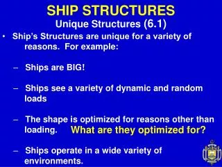
6.1 Unique Aspects of Ship Structures. Ships are BIG! Three dimensional complex shape. Multi-Purpose Support Structure and Skin. Ships see a variety of dynamic and random loads. Ships operate in a wide variety of environments. 6.2 Ship Structural Load.

E N D
6.1 Unique Aspects of Ship Structures • Ships are BIG! • Three dimensional complex shape. • Multi-Purpose Support Structure and Skin. • Ships see a variety of dynamic and random loads. • Ships operate in a wide variety of • environments.
6.2 Ship Structural Load Distributed Forces ; weight & buoyancy Resultant weight force due to the distributed weight G WL B Result Buoyancy force due to the distributed buoyancy < Floating Body in Static Equilibrium> • Two forces are equal in magnitude. • The centroid of the forces are vertically in line.
50 ft barge Distributed Forces Distributed Buoyancy - Buoyant forces can be considered as a distributed force. 2 LT/ft uniformly distributed force
2 LT/ft 50 ft barge 2 LT/ft Distributed Forces Distributed Weight • Weight of ship can be presented as a distributed force. • Case I : Uniformly distributed weight
Distributed Forces Distributed Weight - Case II : Non-uniformly distributed weight 4 LT/ft 10ft 2 LT/ft 2 LT/ft 1 LT/ft 1 LT/ft 50 ft barge 2 LT/ft wFB = 100LT = 2 LT/ft 50ft wFB = FB/L (distributed load = FB/length)
2 LT/ft 2 LT/ft 1 LT/ft 1 LT/ft P R S T O Q 2 LT/ft 2LT/ft 1LT/ft 1LT/ft Shear Stress Shear stress present at points P, Q, R, S & T due to unbalanced forces at top and bottom. Load diagramcan be drawn by summing up the distributed force vertically. 4 LT/ft Q S O P R T Load Diagram P Shear Force at point P
2 LT/ft O P S T Load Diagram Q R 1 LT/ft 1 LT/ft +10 LT Shear Diagram -10 LT Shear Stress Maximum shear stresses occur where the load diagram crosses the x-axis (or equals 0).
Shear Stress How to Reduce Shear Stress of ship To change the underwater hull shape so that buoyancy distribution matches that of weight distribution. - The step like shape is very inefficient with regard to the resistance. - Since the loading condition changes every time, this method is not feasible. To concentrate the ship hull strength in an area where large shear stress exists . This can be done by - using higher strength material - increasing the cross sectional area of the structure.
Longitudinal Bending Stress Longitudinal Bending Moment and Stress Uneven load distribution will produce a longitudinal Bending Moment. Bending Moment - Buoyant force concentrates at bow and stern. - Weight concentrates at middle of ship. The longitudinal bending moment will create a significant stress in the structure called bending stress.
Longitudinal Bending Stress • A ship has similar bending moments, but the buoyancy and many loads are distributed over the entire hull instead of just one point. • The upward force is buoyancy and the downward forces are weights. • Most weight and buoyancy is concentrated in the middle of a ship, where the volume is greatest.
Longitudinal Bending Stress Sagging Bending Moment Weather deck : compression Bow Stern Keel : tension Hogging Weather deck : tension Stern Bow Bending Moment Keel : compression
Longitudinal Bending Stress Sagging & Hogging on Waves Sagging condition Crest Crest Trough Buoyant force is greater at wave crests. Hogging condition Crest Trough Trough
Where: M = Bending Moment I = 2nd Moment of area of the cross section y = Vertical distance from the neutral axis = tensile (+) or compressive(-) stress Longitudinal Bending Stress The longitudinal bending moment creates a significant structural stress called the bending stress
Longitudinal Bending Stress Quantifying Bending Stress y Sagging condition A Compression y A B B Tension Neutral Axis Bending Stress : M : Bending Moment I : 2nd Moment of area of the cross section y : Vertical distance from the neutral axis : tensile (+) or compressive(-) stress
Longitudinal Bending Stress Quantifying Bending Stress Hogging condition y Tension A A B B Compression Neutral Axis Neutral Axis : geometric centroid of the cross section or transition between compression and tension
Longitudinal Bending Stress Example :Bending Stress of Ship Hull Stern Bow Deck A NeutralAxis B Keel cross section Tickness A Deck : Compression Keel : Tension B • Ship could be at sagging condition even in calm water . • Generally, bending moments are largest at the midship area.
Longitudinal Bending Stress Example :Bending Stress of Ship Hull Stern Bow Deck Neutral Axis A B Keel cross section Tickness y A N.A. This ship has lager bending stress at keel than deck. Keel B
Longitudinal Bending Stress Reducing the Effect of Bending stress Bending moment are largest at amidshipof a ship. Ship will experience the greatest bending stress at the deck and keel. The bending stress can be reduced by using: - higher strength steel - larger cross sectional area of longitudinal structural elements
Longitudinal Bending Stress Hull Structure Interaction Bending stress at the superstructure is large because of its distance from the neutral axis. In Sagging or Hogging condition, severe shear stresses between deck of hull and bottom of the superstructure will be created. This shear stresses will cause crack in area of sharp corners where the hull and superstructure connect. This stress can be reduced by an Expansion Joint
Longitudinal Bending Stress Expansion Joint Compression or Tension on bottom Compression or Tension on deck By using Expansion Joint, the super structure will be allowed to flex along with the hull.
Other Loads Hydrostatic Loads Loading associated with hydrostatic pressure Hydrostatic Loads are considerable in submarines Hydrostatic pressure : Torsional Loads Torsional Loads of hull are often insignificant They can have effect on ships with large opening(s) in their weather deck. (e.g., research vessels)
Other Loads Weapon Loads Loading due to explosion of weapons or shock impact, both in air and underwater Naval Vessel should resist these forces Naval vessel will often go through a series of shock trials during initial sea trials.
4LT/ft 3LT/ft 2LT/ft Example Problem 20ft 20ft 10ft 20ft 30ft A B C D 100ft A 100ft long box shaped barge has an empty weight distribution of 2LT/ft. What is the total buoyant force floating the empty barge in calm water? The barge is then loaded with the additional cargo weight distribution shown above. What is the buoyant force distribution in calm water for the loaded barge? At which point, (A, B, C or D) is the barge under the greatest shear stress? Is the barge in a hogging or sagging condition? If a wave hits which peaks at the center of the barge and troughs at the ends, is the condition above mitigated or exacerbated?
4LT/ft 3LT/ft 2LT/ft Example Answer 20ft 20ft 10ft 20ft 30ft A B C D 100ft 0.1LT/ft 2.1LT/ft 1.1LT/ft Load Diagram FB Total Empty=100ft×2LT/ft=200LT FB Total Loaded=200LT+20ft×2LT/ft+30ft×4LT/ft+10ft×3LT/ft=390LT FB Dist’n=390LT/100ft=3.9LT/ft Point A & D: Load Diagram Crosses X- Axis Ends curling up - Sagging (Mitigated by providing additional support at center of barge) 1.9LT/ft 1.9LT/ft
6.3 Ship Structure Structural Components Girder - High strength structure running longitudinally Keel - Large center plane girder - Runs longitudinally along the bottom of the ship Plating - Thin pieces enclosing the top, bottom and side ofstructure - Contributes significantly to longitudinal hull strength - Resists the hydrostatic pressure load (or side impact) Frame - A transverse member running from keel to deck - Resists hydrostatic pressure, waves, impact, etc
Ship Structure Structural Components Floor - Deep frame running from the keel to the turn of the bilge - Frames may be attached to the floors (Frame would be the part above the floor) Longitudinal - Girders running parallel to the keel along the bottom - Intersects floors at right angles - Provides longitudinal strength
Ship Structure Structural Components Stringer - Girders running along the sides of the ship - Typically smaller than a longitudinal - Provides longitudinal strength Deck Beams - Transverse member of the deck frame Deck Girder - Longitudinal member of the deck frame (deck longitudinal)
Framing System Increase ship’s strength by: - Adding framing elements more densely - Increasing the thickness of plating and structural components All this will increase cost, reduce space utilization and allow less mission-related equipment to be added Optimization Longitudinal Framing System Transverse Framing System Combination of Framing System
Framing System Longitudinal Framing System • Longitudinal Framing System : • - Longitudinals are spaced frequently but shallower • - Frames are spaced widely • - Keel, longitudinals, stringers, deck girders, plates • Primary role of longitudinal members : to resist the • longitudinal bending stress due to sagging and hogging. • A typical wave length in the ocean is 300ft. Ships of this length • or greater are likely to experience considerable longitudinal • bending stress. • Ship that are longer than about 300ft (long ship) tend to have a • greater number of longitudinal members than transverse • members.
Framing System Transverse Framing System Transverse Framing System : - Longitudinals are spaced widely but deep. - Frames are spaced closely and continuously Transverse members : frame, floor, deck beam, plating Primary role of transverse members : to resist hydrostatic loads. Ships shorter than 300ft and submersibles
Framing System Combined Framing System Combination of longitudinal and transverse framing system Purpose : - To optimize the structural arrangement for the expected loading - To minimize the cost Typical combination : - Longitudinals and stringers with shallow frame - Deep frame every 3rd or 4th frame
Double Bottoms Two watertight bottoms with a void space in between to withstand - the upward pressure - bending stresses - bottom damage by grounding and underwater shock. The double bottom provides a space for storing - fuel oil - ballast water & fresh water - smooth inner bottom which make it easier to arrange cargo & equipment and clean the cargo hold.
Watertight Bulkheads Large bulkhead which splits the the hull into separate sections Primary role - Stiffening the ship - Reducing the effect of damage The careful positioning the bulkheads allows the ship to fulfill the damage stability criteria. The bulkheads are often stiffened by steel members in the vertical and horizontal directions.
6.4 Modes of Structural Failure 1. Tensile or Compressive Yield Slow plastic deformation of a structural component due to an applied stress greater than yield stress To avoid the yield, Safety factors are considered for ship constructions. Safety factor = 2 or 3 (Maximum stress on ship hull will be 1/2 or 1/3 of yield stress.)
Modes of Structural Failure 2. Buckling Substantial dimension changes and sudden loss of stiffness caused by the compression of long column or plate Buckling load on ship : cargo, waves, impact loads, etc. Ex : Deck buckling : by sagging or hogging, loading on deck Side plate buckling : by waves, shock, groundings column bucking : by excessive axial loading
Modes of Structural Failure 3. Fatigue Failure The failure of a material from repeated application of stress such as from vibration Endurance limit : stress below which will not fail from fatigue Fatigue failure is affected by - material composition (impurities, carbon contents, internal defects) - surface finish - environments (corrosion, salinities, sulfites, moisture,..) - geometry (sharp corners, discontinuities) - workmanship (welding, fit-up) Fatigue generally creates cracks on the ship hull.
Modes of Structural Failure 4. Brittle Fracture A sudden catastrophic failure with little or no plastic deformation Brittle fracture depends on Material: Low toughness & high carbon material Temperature: Material operating below its transition temperature Geometry: Weak point for crack : sharp corners, edges Type / Rate of Loading: Tensile/impact loadings are worse
Modes of Structural Failure 5. Creep • The slow plastic deformation of material due to continuously • applied stresses that are below its yield stress. • Creep is not usually a concern in ship structures.
Example Problem:Identify the following ship structural elements: • ____________ • Strength Members • ____ • __________ • _______ • __________ • _____ • __________ • Strength Members • _____ • _____ • _________ • _______
Example Answer:Identify the following ship structural elements: • TransverseStrength Members • Frame • Floor • Deck Beam • Plating • LongitudinalStrength Members • Keel • Longitudinal • Stringer • Deck Girder • Plating
Example Problem For the following components, what is the primary failure mode of concern and how do we address that concern? • Thick low carbon steel nuclear reactor pressure vessel • Aluminum airplane wings where they join the fuselage • Weapons handling gear • Steel water tower legs
Example Answer Thick low carbon steel nuclear reactor pressure vessel • Brittle Fracture • Operate primarily above transition temperature • Minimize stresses when below transition temperature Aluminum airplane wings where they join the fuselage • Fatigue • Highly polished surfaces • Frequent inspections • Periodic replacements Weapons handling gear • Tensile/compressive yield • Limit loads • Perioidic weight tests • Visual inspections prior to use Steel water tower legs • Buckling/instability • Limit loads • Cross brace
Review of Chapters 4-6 Chapter 4: Stability Chapter 5: Properties of Naval Materials Chapter 6: Ship Structures Review Equation & Conversion Sheet
Chapter 4: Stability • Internal Righting Moment • Curve of Intact Statical Stability • Stability Characteristics from Curve • Effect of Vertical Motion of G on GZ • Effect of Transverse Motion of G on GZ • Damage Stability • Free Surface Correction • Metacentric Height and Stability
Chapter 4 • RM=GZ D=GZ FB • GZeff=G0Z0-G0GvsinF-GvGtcosF-FSCsinF (GZeff=G0Z0-KGsinF-TCGcosF-FSCsinF) • FSC=rtit/(rsVs) • it=lb³/12 (for rectangular tank) • GMeff=GM-FSC=KM-KG-FSC • GZ=GMsinF (for small angles) • Damage Stability analyzed using added weight method • Positive, Neutral, Negative Stability
Curve of Intact Statical Stability Righting Arm (GZ) Max Righting Arm (GZmax) (×D=Max Righting Moment) Angle of GZmax Dynamical Stability =DòGZdf Slope~tender/stiff Heeling Angle Range of Stability
Chapter 5: Properties of Naval Materials • Classifying Loads • Stress and Strain • Stress-Strain Diagrams and Material Behavior • Material Properties • Non-Destructive Testing • Other Engineering Materials
Chapter 5 • Stress: s=F/A (lb/in², psi or ksi) • Elongation: e=L-L0; Strain: e=e/L0 (ft/ft) • Elastic Modulus: E=s/e (lb/in², psi, ksi) UTS Elastic Region Strain Hardening sy Fracture Plastic Region s Stress Material Toughness Slope=E e Strain Stress/Strain Diagram