Drilling Methods
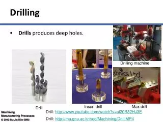
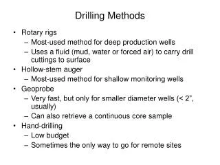
Drilling Methods. Rotary rigs Most-used method for deep production wells Uses a fluid (mud, water or forced air) to carry drill cuttings to surface Hollow-stem auger Most-used method for shallow monitoring wells Geoprobe Very fast, but only for smaller diameter wells (< 2”, usually)

Drilling Methods
E N D
Presentation Transcript
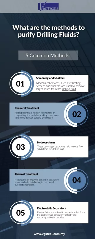
Drilling Methods • Rotary rigs • Most-used method for deep production wells • Uses a fluid (mud, water or forced air) to carry drill cuttings to surface • Hollow-stem auger • Most-used method for shallow monitoring wells • Geoprobe • Very fast, but only for smaller diameter wells (< 2”, usually) • Can also retrieve a continuous core sample • Hand-drilling • Low budget • Sometimes the only way to go for remote sites
This is a truck-mounted “Geoprobe”. This unit uses pneumatic pressure to push a 1” monitoring well up to 50 feet into the ground in minutes, with a minimum of disturbance of the aquifer. Continuous drill core can be retrieved as the hole is drilled. This is a modular unit made by the same company that can be mounted on the back of a tractor or ATV. http://www.enviroprobe.com/pages/1/index.htm
Drilling wells by hand This grad student was able to install several 1.5” monitoring wells into a remote wetland where it would be impossible to bring a drill rig. 15 feet is about the deepest you can get using a soil auger. This works best for loamy or clay-rich soils. Sand + gravel will cave into the hole, especially below the water table.
Installing a 1” well GW sampling using a peristaltic pump
Monitoring wells for agency work • Drill the hole • Build the well screen and casing • Well completion - sand pack, bentonite seal, surface seal, security (lock) • Well development • pump or bail water by hand until clear • determine specific capacity (pumping rate/drawdown) - submit well data to State agency database • Monitoring - water levels - water quality
Installing a sand filter around the screen of the well. The well is completed from bottom to the top, as the hollow-stem auger is slowly pulled back out of the ground.
Well screens Reinforced continuous slot screen (stainless steel), for deep wells where money is not an issue. PVC well screen. The screen slot size varies, depending on the average grain size of the aquifer. The screen is overlain by “blank casing”.
http://www.solinst.com/Res/papers/401K.html To monitor for vertical gradients in hydraulic head or water quality, one can install clustered wells, nested wells (in the image, 4 wells are shown in the same hole, each screen separated by a bentonite seal), or a more expensive multilevel system that allows retrieval of gw from different depths in the same well.
mini-piezometers h stream stream L gw gw gaining losing/perched These can be installed by hand and consist of a stainless steel pipe driven into the ground with an open bottom. By measuring the hydraulic head inside the pipe, one can determine if a stream is gaining or losing.
Pumping test: Miles Crossing, Montana (May, 2004) This test used a 1-HP submersible pump powered by a generator, and a network of 6 monitoring wells, each equipped with a pressure transducer hooked to a central data-logger. The aquifer is partially confined.
Closer look at the datalogger (blue) and students installing the pump. The wells are 2” PVC.
Mine tailings Students monitored wells close to a nearby creek to see if water from the creek was drawn into the cone of depression.
Slug tests Figure 1. Typical well configuration for a slug test in an unconfined aquifer. Good web resource: http://www.aquifertest.com/forum/slug.htm
Attacking the great problems of the planet: The need for new structures and new teams A Geochemist's Perspective Dr. Bill Fyfe Monday, March 21, 2005 Concordia University Hall Building, Room H-763 18:00