Download
1 / 66
680 likes | 871 Vues
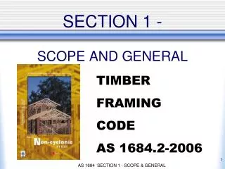
SECTION 1 - SCOPE AND GENERAL. TIMBER FRAMING CODE AS 1684.2-2006. 1.1 SCOPE.

E N D
SECTION 1 -SCOPE AND GENERAL TIMBER FRAMING CODE AS 1684.2-2006 AS 1684 SECTION 1 - SCOPE & GENERAL
1.1 SCOPE This Standard specifies requirements for building practice and the selection, placement and fixing of the various structural elements used in the construction of timber-framed Class 1 and Class 10 Buildings as defined by the Building Code of Australia *The Standard also applies to alterations and additions to these buildings. AS 1684 SECTION 1 - SCOPE & GENERAL
Building Classes Class 1(a) - Detached house Attached dwellings (Terrace houses, Villas etc.) Class 1(b) - Boarding house • not more than 300 sq. mtrs • not more than 12 residents Class 10 - Outbuildings (garages, carports etc.) AS 1684 SECTION 1 - SCOPE & GENERAL
Other Building Classes • Class 2 - Building containing 2 or more • sole occupancy units. • Class 3 - Boarding house, Guest house etc. • • For aged, disabled, children • • Residential part of hotel, motel, school, health care building. • Class 4 - The residential part of a • Class 5,6,7,8,9 building. AS 1684 SECTION 1 - SCOPE & GENERAL
Other Building Classes Class 5 - Offices Class 6 - Shops Class 7 - Storage, Carparks Class 8 - Factories, Workshops Class 9 - Public Buildings AS 1684 SECTION 1 - SCOPE & GENERAL
1.4 Limitations The information contained in this Standard is provided specifically for conventional timber-framed buildings and is applicable to single-and two-storey construction built within the limits or parameters given in Clauses 1.4.2 to 1.4.10 and Figure 1.1. AS 1684 SECTION 1 - SCOPE & GENERAL
1.4.2(a) Wind Classification The height limitation of 8.5 m to the ridge Where the wind classification is determined from AS 4055, the maximum building height limitation of 8.5m given in AS 4055 shall apply to this Standard. AS 1684 SECTION 1 - SCOPE & GENERAL
1.6.2 Wind Classification Non-cyclonic AS 1684 SECTION 1 - SCOPE & GENERAL
1.4.3 Plan Building shapes shall be essentially rectangular, square, L-shaped or a combination of essentially rectangular elements including splayed-end and boomerang-shaped buildings. There is no major limitation on the shape of buildings. Exceptions may include dome shaped buildings. AS 1684 SECTION 1 - SCOPE & GENERAL
1.4.4 Number of storeys The maximum number of storeys of timber framing shall not exceed two. The building shown opposite is considered to be ‘two storeys of timber framing’. See comments Section 2 - Clause 2.7.8 for more information. AS 1684 SECTION 1 - SCOPE & GENERAL
1.4.3 Plan FIGURE 1.1 (b) Plan AS 1684 SECTION 1 - SCOPE & GENERAL
1.4.5 Width The maximum width of building shall be 16000 mm, excluding eaves. This limitation on width only limits the distance between the ‘pitching points’ of the roof. AS 1684 SECTION 1 - SCOPE & GENERAL
Use of the timber span tables may also limit this width. e.g. the timber span tables only cater for Roof Load Widths up to 7.5 m. Refer Section 2.6 for more details on RWL. AS 1684 SECTION 1 - SCOPE & GENERAL
1.4.6 Wall height The maximum wall height shall be 3000 mm (floor to ceiling) as measured at common external walls, i.e. not gable or skillion ends. AS 1684 SECTION 1 - SCOPE & GENERAL
1.4.6 Wall height NOTES: 1 The Span Tables for studs given in the Supplements provide for stud heights in excess of 3000 mm to cater for gable, skillion and some other design situations where wall heights, other than those of common external walls, may exceed 3000 mm. A2 AS 1684 SECTION 1 - SCOPE & GENERAL
1.4.6 Wall height NOTES: (cont) 2 Building height limitations apply where wind classification is determined using AS 4055 (see Clause 1.6.2). A2 The limitation of 8.5 m to ridge is used by AS 4055 to determine the wind speed so if the wind classification is determined using AS 4055 this limitation will apply. AS 1684 SECTION 1 - SCOPE & GENERAL
1.4.6 Wall height NOTES: (cont) 3 The provisions contained in this Standard may also be applicable to houses with external wall heights up to 3600 mm where appropriate consideration is given to the effect of the increased wall height on racking forces, reduction to bracing wall capacities, overturning and uplift forces, shear forces and member sizes. A4 AS 1684 SECTION 1 - SCOPE & GENERAL
1.4.7 Roof Pitch The maximum roof pitch shall be 35° (70:100). 35O 35O AS 1684 SECTION 1 - SCOPE & GENERAL
1.4.8 Spacing of bracing For single or upper storeyThe spacing of bracing elements, measured at right angles to elements, shall not exceed 9000 mm. for N1 & N2. For wind classifications N3, N4, C1, C2 & C3 the spacing of bracing elements is determined in accordance with Clause 8.3.6.7 (see section 8, pg 149) AS 1684 SECTION 1 - SCOPE & GENERAL
1.4.8 Spacing of bracing For the lower storey of two storey or subfloor of single or two storey construction, bracing walls shall be spaced in accordance with Clause 8.3.5.9. (see section 8, pg 139) AS 1684 SECTION 1 - SCOPE & GENERAL
1.4.9 Roof types Roof construction shall be hip, gable, skillion, cathedral, trussed or pitched or in any combination of these. AS 1684 SECTION 1 - SCOPE & GENERAL
1.4.10 Building Masses Building masses appropriate for the member being designed shall be determined prior to selecting and designing from the Span Tables in the Supplements. Where appropriate, the maximum building masses relevant to the use of each member Span Table are noted under the Table. AS 1684 SECTION 1 - SCOPE & GENERAL
1.4.10 Building Masses (cont’d) For the design of most timber members, other than ‘rafters, purlins, intermediate beams, ridge beams and underpurlins’ for pitched and cathedral roofs, selecting a Sheet roof or a Tile roof will be all that is required to ‘determine the appropriate building mass’. AS 1684 SECTION 1 - SCOPE & GENERAL
1.4.10 Building Masses (cont’d) Where a table asks for an input of ‘Tile Roof’ or ‘Sheet Roof’, the maximum mass assumed by the table is 40 kg per square metre for a Sheet roof and 90 kg per square metre for a Tile roof. AS 1684 SECTION 1 - SCOPE & GENERAL
1.4.10 Building Masses (cont’d) For rafters or purlins, intermediate beams, ridge beams and underpurlins, for pitched and cathedral roofs, the appropriate roof masses (weight) for various members will need to calculated using Appendix B of AS 1684. AS 1684 SECTION 1 - SCOPE & GENERAL
1.4.10 Building Masses (cont’d) For rafters or purlins, the ‘supported materials’ will include the weight of the roofing material, roof battens, sarking and/or insulation plus ceiling battens and ceiling sheeting for a cathedral roof.` The mass of a member being considered has been accounted for in the design of that member. AS 1684 SECTION 1 - SCOPE & GENERAL
1.6 FORCES ON BUILDINGS The design of framing members may be influenced by the wind forces that act on the specific members. When using Span Tables in the Supplements, the appropriate wind classification (e.g. N2) together with the stress grade shall be established prior to selecting the appropriate supplement to obtain timber member sizes. AS 1684 SECTION 1 - SCOPE & GENERAL
1.6 FORCES ON BUILDINGS (cont’d) Statements expressed in mandatory terms in Notes to the Span Tables are deemed to be requirements of this Standard. All framing members shall be adequately designed and joined to ensure suitable performance under the worst combinations of dead, live, wind and earthquake loads. AS 1684 SECTION 1 - SCOPE & GENERAL
1.6 FORCES ON BUILDINGS (cont’d) Assumptions used for forces, load combinations and serviceability requirements of framing members are given in AS 1684.1. Figure 1.2 indicates forces applied to timber-framed buildings that shall be considered. AS 1684 SECTION 1 - SCOPE & GENERAL
1.6 FORCES ON BUILDINGS (cont’d) The main forces acting on buildings are: • Dead Loads - the forces arising from the weight of the building components themselves. • Live Loads - the forces arising from the weight of persons using the building and moveable furniture. • Wind Loads - the forces arising from - gales, thunderstorms & tropical cyclones. AS 1684 SECTION 1 - SCOPE & GENERAL
(a) Gravity loads (b) Uplift wind loads NOTE: For clarity, earthquake and snow loads are not shown (see Clause 1.5). FIGURE 1.2 LOADS ON BUILDINGS AS 1684 SECTION 1 - SCOPE & GENERAL
1.6 FORCES ON BUILDINGS (cont’d) Forces on buildings produce different effects on a structure. Each effect shall be considered individually and be resisted. Figure 1.3 summarizes some of these actions. This Standard takes account of these. AS 1684 SECTION 1 - SCOPE & GENERAL
Racking (wall deformation) RACKING force is resisted by BRACING. AS 1684 SECTION 1 - SCOPE & GENERAL
OVERTURNING is resisted by NOMINAL and/orTIE-DOWN CONNECTIONS. AS 1684 SECTION 1 - SCOPE & GENERAL
SLIDING (Shear Forces) is resisted by NOMINAL and/or TIE-DOWN CONNECTIONS and in some situations extra fixings. AS 1684 SECTION 1 - SCOPE & GENERAL
UPLIFT is resisted by NOMINAL and/orTIE-DOWN CONNECTIONS. AS 1684 SECTION 1 - SCOPE & GENERAL
1.7 LOAD PATHS OFFSETS AND CANTILEVERS Roof loads, ceiling loads, wall loads and floor loads shall, where applicable, be transferred through the timber frame to the footings by the most direct route. For floor framing, the limitations imposed regarding the support of point loads and the use of offsets and cantilevers are specified in Section 4. AS 1684 SECTION 1 - SCOPE & GENERAL
1.7 LOAD PATHS OFFSETS AND CANTILEVERS(cont’d) NOTES: 2 Floor members designed as ‘supporting floor load only’ may support a loadbearing wall (walls supporting roof loads) where the loadbearing wall occurs directly over a support or is within 1.5 times the depth of the floor member from the support (see also to Clause 4.3.1.2 and Clause 4.3.2.3). AS 1684 SECTION 1 - SCOPE & GENERAL
1.7 LOAD PATHS OFFSETS AND CANTILEVERS(cont’d) 3. Other members supporting roof or floor loads where the load occurs directly over the support or is within 1.5 times the depth of the member from the support do not require to be designed for that load. AS 1684 SECTION 1 - SCOPE & GENERAL
This may be any member that supports roof and/or floor loads AS 1684 SECTION 1 - SCOPE & GENERAL
In a timber frame, loads are frequently taken to the foundations through horizontal members designed to transfer these loads, such as roof beams, hanging & strutting beams, lintels, floor joist and bearers. As these horizontal members concentrate the loads at their ends, care must be taken to ensure that, if these concentrated loads are in turn supported by another horizontal member, that this member is designed accordingly. AS 1684 SECTION 1 - SCOPE & GENERAL
An example of this is where a strutting beam or girder truss is supported by a lintel. This lintel needs to be designed for this point load. The jamb studs will also need to be designed to carry this extra load as well as the structure that supports these jamb studs. AS 1684 SECTION 1 - SCOPE & GENERAL
1.8 DURABILITY Structural timber used in accordance with this Standard shall have the level of durability appropriate for the relevant climate and expected service life and conditions including exposure to insect attack or to moisture which could cause decay. AS 1684 SECTION 1 - SCOPE & GENERAL
1.9 DIMENSIONS Timber dimensions throughout this Standard are stated by nominating the depth (the dimension that carries the load)of the member first followed by its breadth (see Figure 1.6); e.g. 90 35 mm (studs, joists etc.), 45 70 (wall plates, battens, etc.) AS 1684 SECTION 1 - SCOPE & GENERAL
1.10 BEARING The minimum bearing for specific framing members (bearers, lintels, hanging beams, strutting beams, combined strutting / hanging beams, counter beams, combined counter/strutting beams and verandah beams) shall be as given in the Notes to the Span Tables of the Supplements, as appropriate. AS 1684 SECTION 1 - SCOPE & GENERAL
1.10 BEARING In all other cases, except for battens, (roof and ceiling battens) framing members shall bear on to their supporting element, a minimum of 30 mm at their ends or 60 mm at the continuous part of the member, by their full breadth (thickness). Reduced bearing area shall only be used where additional fixings are provided to give equivalent support to the members. A3 AS 1684 SECTION 1 - SCOPE & GENERAL
1.10 BEARING Where the bearing area is achieved using a non-rectangular area such as a splayed joint, the equivalent bearing area shall not be less than that required above. AS 1684 SECTION 1 - SCOPE & GENERAL
1.11 STRESS GRADES All structural timber used in conjunction with this Standard shall be stress graded in accordance with the relevant Australian Standard. All structural timber to be used in conjunction with this Standard shall be identified in respect of stress grade. AS 1684 SECTION 1 - SCOPE & GENERAL