Future Hardware for Trigger and DAQ systems (xTCA)
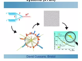
Future Hardware for Trigger and DAQ systems (xTCA). David Cussans, Bristol. Science Motivation. 2008. (100k) Haystacks. 1GHz. 1MHz. 2009. 1kHz. Event rate. Cross-section (interaction probability). 2010. 1Hz. 1/hr. 2011-2. 1/wk. Needle. ‘Typical’ 2012 Bunch Crossing.

Future Hardware for Trigger and DAQ systems (xTCA)
E N D
Presentation Transcript
Future Hardware for Trigger and DAQ systems (xTCA) • David Cussans, Bristol
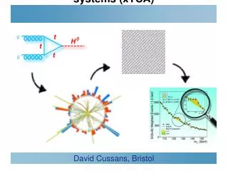
Science Motivation 2008 (100k)Haystacks 1GHz 1MHz 2009 1kHz Event rate Cross-section(interaction probability) 2010 1Hz 1/hr 2011-2 1/wk Needle
Detector Design • LHC detector mission • Find and measure incredibly rare events... (1/hr) • Against almost indistinguishable background of common events (1kHz) • In an environment of incredibly high-rate background (1GHz) • Detector characteristics • Fast response time • Unique crossing-ID required -> 25ns time resolution • Large area and hermeticity; lowest possible material for inner detectors • High granularity • Efficient pattern recognition -> For low occupancy -> 10k’s to M’s of channels • Good resolution, low noise, high dynamic range • Energy resolution in calorimetry; (interpolated) position information in tracking • Environment for on-detector electronics • Highly constrained in terms of space, cooling, access, services • Electromagnetically noisy & high radiation dose in places
Front-End Electronics • e.g. CMS ECAL front end electronics (UK development) • ~80000 channels, 40Ms/s, 12b resolution, 16 b dynamic range • Based on two custom rad-hard CMS ASICs, 0.25u technology • Along with carefully qualified commercial optoelectronics, sensors Digital sampling Pipeline storage Local processing Trigger / DAQoutputs Analogue VFE Control / timing
On Detector Electronics • Design dictated by need to fit in detector and cope with environment.
Off Detector Electronics • Receive data from detector, filter/process, send for storage • Different constraints from on-detector • Can use standard format electronics • Sub-racks housed in larger racks ( sub-racks frequently 19-inches ). • Racks provide power, cooling • Standards change: NIM (1966), CAMAC (1976), FASTBUS (1986), VMEp (1998), xTCA(20xx) ..... • xTCA for HEP proposed at least ten years ago • ( e.g.An Initial Look at a CMS Level-1 Trigger for an Upgraded LHC, D.Cussans et. al.,10th Workshop on Electronics for LHC and Future Experiments, Boston, MA, USA, 13 - 17 Sep 2004, pp.73-76 DOI 10.5170/CERN-2004-010.73 ) • ... but only in last few years has “critical mass” developed.
Why Change? • Current generation of experiments mainly use VME. Why change? • Chasing more massive particles and smaller cross-sections --> need larger machines producing (much) more data. • Last decade revolution in analog, digital, communication technologies opened up new opportunities. • Parallel multi-drop bus --> point-to-point gigabit serial links. • Follow lead from other areas: PCI-->PCIe , Parallel printer --> USB, PATA--> SATA • Programmable FPGA’s allow much more functionality than discrete logic components. Micro-controllers now cheap • Multilayer board design enables Gigabit backplanes >10 GHz bandwidth • –Integrated SERDES communications obsolete parallel bus backplanes • –LVDS balanced multi Gbps backplanes minimize discrete switch blades • –Intelligent platform management diagnoses enterprise wide problems to board level, initiates corrective action • –Redundant architectures => shelf Availability of 5 nines or better (0,99999)
Acknowledgements • Slides/material taken from • Introduction to MicroTCARay Larsen SLAC MicroTCA Review June 4-5, 2012 • xTCA interest grouphttps://twiki.cern.ch/twiki/bin/view/XTCA/WebHome • Mark Pessaresi (FC7) , Andy Rose, Greg Isles (MP7) • Dave Newbold (IPBus)
Will xTCA dissapear? • ATCA (and especially uTCA) new standard, but don’t look as if they are “here today, gone tomorrow”
Currently Vadatech VT892 quite common in CMS ( variant with vertical airflow )
uTCA for Physics (MTCA.4) • New variant to allow rear-transition modules ( RTM)
Examples of uTCA Board • CMS-heavy (apologies) • Could find many more examples from XFEL, FAIR, etc. • Module aimed at test-bench , beam-test work: GLIB • Module aimed at being a “Front End” board that receives data from detector (FC7) • Module aimed at data processing for e.g. trigger (MP7)
FC7 Prototype Front-end AMC • ~10GHz (MP7) • Good performance (weave misaligned with PCB) • Constant low dielectric loss tangent - EPSI-N4000 13 Nelco • 16 layers
FC7 - Input from Detector • Custom input circuitry on “FPGA Mezzanine Cards”
Generic uTCA Test-platform (GLIB,CERN) • Test-bench , beam-test • Two FMC (FPGA Mezzanine Card) site, SFP cages Stefan Haas, MTCA Workshop, DESY, 12. Dec. 2012
Generic uTCA Test-platform (GLIB,CERN) Stefan Haas Stefan Haas, MTCA Workshop, DESY, 12. Dec. 2012 • Available from CERN • Firmware/software skeleton available (uses IPBus)
CMS uTCA Trigger Processor: MP7 • MP7 card: building block for L1 and DAQ systems • Large Virtex-7 series FPGA (6 Billion transistors); 144Mb fast RAM • 1.4Tb/s of low-latency IO on optical links; 50Gb/s backplane IO • Integrated into industry-standard uTCA software / hardware environment • Will future L1 / FE look more like a commercial switch fabric? A. Rose, Imperial
Setup and Control • Current generation of VME crates typically use VME backplane to set-up/configure boards. • Detector data moved around on custom back-plane/ rear-transition-modules • Need to replace this functionality in an xTCA system • One solution is IPBus • Developed for use in CMS upgrades. • Now being adopted by several other experiments
IPBus • IPbus is a simple, IP-based control protocol • Originally created by Jeremy Mans, et al in 2009/2010 • S/w and f/w development is being done by a UK collaboration University of Bristol and Imperial College London, Rutherford Appleton Laboratory • Protocol describes basic transactions needed to control h/w Read/write, non-incrementing read/write, etc, etc. • UDP is the recommended transport implementation • Easiest to implement in firmware • Uses relatively few FPGA resources • Interface inside FPGA looks like a A32/D32 bus. (sub-set of Wishbone) • See https://svnweb.cern.ch/trac/cactus
Board Start-up (MMC) • ATCA, uTCA boards need to negotiate with power supply when inserted in crate. • Allows hot-swap of boards • means that without MMC an AMC won’t do anything when inserted in crate. • Strongly recommend: get hold of somebody else’s code or hardware for MMC. See e.g. https://espace.cern.ch/ph-dep-ESE-BE-uTCAEvaluationProject/MMC_project/default.aspx
Summary • Prediction is very difficult, especially about the future • (ascribed to Neils Bohr ) • .... but it does look like the next generation of off-detector electronics for large HEP experiments will use xTCA • Has reached critical mass. Baseline for CMS upgrades, used for XFEL, at FAIR. • High performance, but a rather complex system • Use off-the-shelf components where possible • e.g. MMC, setup/control firmware