Download
1 / 28
280 likes | 463 Vues
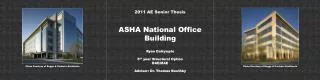
2011 AE Senior Thesis. ASHA National Office Building. Ryan Dalrymple 5 th year Structural Option BAE/MAE Advisor: Dr. Thomas Boothby. Photo Courtesy of Boggs & Partners Architects. Photo Courtesy of Boggs & Partners Architects. Presentation Outline. Introduction. Introduction

E N D
2011 AE Senior Thesis ASHA National Office Building Ryan Dalrymple 5th year Structural Option BAE/MAE Advisor: Dr. Thomas Boothby Photo Courtesy of Boggs & Partners Architects Photo Courtesy of Boggs & Partners Architects
Presentation Outline Introduction Introduction Thesis Objectives/Goals Structural Depth Floor System Comparison Gravity System Design ETABS Model Recalculation of Seismic Loads Lateral Design Foundation Check Construction Management Breadth Cost Analysis Schedule Analysis Final Summary/Conclusions Building Name: ASHA National Office Location: 2200 Research Blvd Rockville, MD 20850 Occupant: American-Speech-Language-Hearing Association Occupancy Type: Office Building Size: 133,870 sq. ft. Number of Stories: 5 stories above grade/2 levels of underground parking Dates of Construction: April 2006 – December 2007 Project Cost: $48,000,000 www.bing.com
Introduction • Structural System • Gravity System of Office Tower • Composite steel beam floor system • 3 ½” NW conc. on 2” 18 gauge composite metal deck • 3/4” diameter shear studs • Typical beam sizes: W21x44, W14x22, W18x35 • Columns are W12 and W14 members • Gravity System of Subgrade Parking Structure • Two-way flat slab system with drop panels • 9” thick slab with 5 ½” thick drop panels • Drop panels typically 7’-0”x9’-0” and 10’-0x10’-0” • 5000 psi concrete • Typical concrete column sizes: 18”x30” and 24”x21” • Lateral System • 4 shear walls/braced frames • Shear walls in subgrade parking structure • Braced frames in office tower • Foundation • Primarily spread footings • Range from 4’-0”x4’-0” to 11’-0”x11’-0” • 12” to 36” deep Typical Framing Plan
Introduction • Structural System • Gravity System of Office Tower • Composite steel beam floor system • 3 ½” NW conc. on 2” 18 Ga. composite metal deck • 3/4” diameter shear studs • Typical beam sizes: W21x44, W14x22, W18x35 • Columns are W12 and W14 members • Gravity System of Subgrade Parking Structure • Two-way flat slab system with drop panels • 9” thick slab with 5 ½” thick drop panels • Drop panels typically 7’-0”x9’-0” and 10’-0x10’-0” • 5000 psi concrete • Typical concrete column sizes: 18”x30” and 24”x21” • Lateral System • 4 shear walls/braced frames • Shear walls in subgrade parking structure • Braced frames in office tower Parking Level Framing Plan • Foundation • Primarily spread footings • Range from 4’-0”x4’-0” to 11’-0”x11’-0” • 12” to 36” deep
Introduction • Structural System • Gravity System of Office Tower • Composite steel beam floor system • 3 ½” NW conc. on 2” 18 Ga. composite metal deck • 3/4” diameter shear studs • Typical beam sizes: W21x44, W14x22, W18x35 • Columns are W12 and W14 members • Gravity System of Subgrade Parking Structure • Two-way flat slab system with drop panels • 9” thick slab with 5 ½” thick drop panels • Drop panels typically 7’-0”x9’-0” and 10’-0x10’-0” • 5000 psi concrete • Typical concrete column sizes: 18”x30” and 24”x21” • Lateral System • 4 shear walls/braced frames • Shear walls in subgrade parking structure • Braced frames in office tower • Foundation • Primarily spread footings • Range from 4’-0”x4’-0” to 11’-0”x11’-0” • 12” to 36” deep Typical Framing Plan
Introduction • Structural System • Gravity System of Office Tower • Composite steel beam floor system • 3 ½” NW conc. on 2” 18 Ga. composite metal deck • 3/4” diameter shear studs • Typical beam sizes: W21x44, W14x22, W18x35 • Columns are W12 and W14 members • Gravity System of Subgrade Parking Structure • Two-way flat slab system with drop panels • 9” thick slab with 5 ½” thick drop panels • Drop panels typically 7’-0”x9’-0” and 10’-0x10’-0” • 5000 psi concrete • Typical concrete column sizes: 18”x30” and 24”x21” • Lateral System • 4 shear walls/braced frames • Shear walls in subgrade parking structure • Braced frames in office tower • Foundation • Primarily spread footings • Range from 4’-0”x4’-0” to 11’-0”x11’-0” • 12” to 36” deep Partial Foundation Plan
Introduction • Architecture • Building façade of office tower consists of a window wall system and precast concrete spandrels • Plaza level spaces: • Lobby • Conference Rooms • Pre-function Space • Café and Kitchen • Gym • 2nd – 5th Floor spaces: • Offices • Cubicles • One of the main architectural themes is curves to mimic the sound waves in the ASHA logo www.asha.org Pre-function Space Curved Glass Curtain Wall
Presentation Outline Thesis Objectives/Goals Introduction Thesis Objectives/Goals Structural Depth Floor System Comparison Gravity System Design ETABS Model Recalculation of Seismic Loads Lateral Design Foundation Check Construction Management Breadth Cost Analysis Schedule Analysis Final Summary/Conclusions • Investigate the feasibility of changing the structural system of the office tower to reinforced concrete • Creates continuity with the concrete parking structure below • May eliminate the need for shear walls/braced frames • Architectural Breadth (Not Presented) • Explore impact of additional columns needed for two-way flat slab floor system • Create layout for Plaza level floor plan • Construction Management Breadth (Presented) • Cost Analysis • Schedule Analysis • Structural Depth • Explore two different floor systems • Two-way flat slab w/ drop panels • One-way slab and beam • Design gravity system • Design floor system • Design columns • Design lateral system • Determine if gravity members are adequate to resist gravity loads • Design shear walls if needed • Explore impact on foundations
Presentation Outline Floor System Comparison Introduction Thesis Objectives/Goals Structural Depth Floor System Comparison Gravity System Design ETABS Model Recalculation of Seismic Loads Lateral Design Foundation Check Construction Management Breadth Cost Analysis Schedule Analysis Final Summary/Conclusions • Two-way Flat Slab System w/ Drop Panels • 9” slab w/ 4 ½” drop panels • Drop panels generally 9’-0”x7’-0” • Concrete compressive strength of 5000 psi • Reinforcing designed to be #5 bars • Column strip and middle strip reinforcing designed in spSlab spSlab Reinforcement Diagram Col. Line C spSlab Model Col. Line C
Floor System Comparison • Two-way Flat Slab System w/ Drop Panels • 9” slab w/ 4 ½” drop panels • Drop panels generally 9’-0”x7’-0” • Concrete compressive strength of 5000 psi • Reinforcing designed to be #5 bars • Column strip and middle strip reinforcing designed in spSlab Typical Framing Plan – Two-way Flat Slab spSlab Model Col. Line C
Floor System Comparison • One-Way Slab and Beam System • 9” slab w/ #5 bars at 6” o.c. • Concrete compressive strength of 5000 psi • Flexural and shear reinforcing for one-way beams designed using spBeam • Beams are typically 18” wide and range from 12” to 26” deep spBeam Reinforcement Diagram Col. Line C spBeam Model Col. Line C
Floor System Comparison • One-Way Slab and Beam System • 9” slab w/ #5 bars at 6” o.c. • Concrete compressive strength of 5000 psi • Flexural and shear reinforcing for one-way beams designed using spBeam • Beams are typically 18” wide and range from 12” to 26” deep Typical Framing Plan – One-way Slab and Beams spBeam Model Col. Line C
Floor System Comparison • One-Way Slab and Beam System • 9” slab w/ #5 bars at 6” o.c. • Concrete compressive strength of 5000 psi • Flexural and shear reinforcing for one-way beams designed using spBeam • Beams are typically 18” wide and range from 12” to 26” deep Typical Framing Plan – One-way Slab and Beams spBeam Model Col. Line C
Floor System Comparison Cost Comparison Two-way flat slab system ~$20.05/sq. ft. One-way slab and beam system ~$20.29/sq. ft. Floor Plan Impacts Two-way flat slab system 25 additional columns One-way slab and beam system No additional columns Plaza Level Floor Plan One-way slab and beam system ultimately chosen for thesis redesign!
Presentation Outline Gravity System Design Introduction Thesis Objectives/Goals Structural Depth Floor System Comparison Gravity System Design ETABS Model Recalculation of Seismic Loads Lateral Design Foundation Check Construction Management Breadth Cost Analysis Schedule Analysis Final Summary/Conclusions • Beam layout created • Beam and column widths generally kept the same for constructability • Four transfer girders required, which were designed using spBeam Typical Framing Plan
Gravity System Design • Column Design • Columns designed using spColumn • Columns spliced once at level 4 • Typical column sizes below splice: • Interior: 18x24 in • Exterior: 18x21 in • Typical column sizes above splice: • Interior: 18x20 in • Exterior: 18x18 in
Gravity System Design • Column Design • Columns designed using spColumn • Columns spliced once at level 4 • Typical column sizes below splice: • Interior: 18x24 in • Exterior: 18x21 in • Typical column sizes above splice: • Interior: 18x20 in • Exterior: 18x18 in
ETABS Model Presentation Outline • The self-weight of the columns and beams is accounted for in the model • Rigid end zones are applied to all beams with a reduction of 50% • The slabs are considered to act as rigid diaphragms • The self-weight of the slab is applied as an additional area mass on the rigid diaphragm • P-∆ effects are considered • The moment of inertia for columns = 0.7Ig • The moment of inertia for beams = 0.35Ig • The compressive strength of all concrete is 5000 psi Introduction Thesis Objectives/Goals Structural Depth Floor System Comparison Gravity System Design ETABS Model Recalculation of Seismic Loads Lateral Design Foundation Check Construction Management Breadth Cost Analysis Schedule Analysis Final Summary/Conclusions
Recalculation of Seismic Loads Presentation Outline Introduction Thesis Objectives/Goals Structural Depth Floor System Comparison Gravity System Design ETABS Model Recalculation of Seismic Loads Lateral Design Foundation Check Construction Management Breadth Cost Analysis Schedule Analysis Final Summary/Conclusions • Building weight and seismic loads calculated by hand • R = 3.0 for ordinary concrete moment frame • Fundamental periods obtained from ETABS along principle axes exceeded CuTa • CuTa was used as the design period to calculate seismic loads
Lateral Design Presentation Outline Introduction Thesis Objectives/Goals Structural Depth Floor System Comparison Gravity System Design ETABS Model Recalculation of Seismic Loads Lateral Design Foundation Check Construction Management Breadth Cost Analysis Schedule Analysis Final Summary/Conclusions • Drift and Displacement Check • Allowable seismic story drift for a building in occupancy category II is 0.02hsx • Accepted standard for total building displacement for wind loads is L/400
Lateral Design • Drift and Displacement Check • Allowable seismic story drift for a building in occupancy category II is 0.02hsx • Accepted standard for total building displacement for wind loads is L/400
Lateral Design • Lateral Design of Beams and Columns • Beams and columns checked to determine if they are sufficient to resist wind and seismic loads • Moments on beams due to wind and seismic loads obtained from ETABS and input into spBeam models • Axial loads and moments on columns due to wind and seismic loads input into spColumn • Conclusions • Shear reinforcing had to be increased in half of the beams • Top reinforcing had to be increased for a few beams • Bottom reinforcing sufficient for all beams • Some edge beams in E-W direction had to be increased in size • Columns did not have to be upsized • Reinforcing had to be increased in some columns Typical Framing Plan • Inherent moment resistance of concrete structure is sufficient to resist lateral loads • Shear walls are not needed!
Foundation Check Presentation Outline Introduction Thesis Objectives/Goals Structural Depth Floor System Comparison Gravity System Design ETABS Model Recalculation of Seismic Loads Lateral Design Foundation Check Construction Management Breadth Cost Analysis Schedule Analysis Final Summary/Conclusions • The spread footing at G-3 was redesigned for additional dead load from concrete structure • Existing 11’-0”x11’-0” footing had to be increased to 12’-0”x12’-0” • Reinforcing was designed by hand • Punching shear was checked for the 36” deep footing and was found to be adequate Partial Foundation Plan
Construction Management Breadth Presentation Outline Introduction Thesis Objectives/Goals Structural Depth Floor System Comparison Gravity System Design ETABS Model Recalculation of Seismic Loads Lateral Design Foundation Check Construction Management Breadth Cost Analysis Schedule Analysis Final Summary/Conclusions • Cost Analysis • Cost information for existing structure obtained from Davis Construction • Costs obtained from Davis Construction were adjusted using historical cost indices found in RS Means • Detailed concrete, formwork, and reinforcement takeoffs were done by hand • RS Means used to obtain unit prices for concrete structure
Construction Management Breadth Cost Comparison Existing Steel Structure Cost: $5,475,712 Concrete Redesign Cost: $6,000,013
Construction Management Breadth Presentation Outline Construction Schedule – Concrete Redesign Introduction Thesis Objectives/Goals Structural Depth Floor System Comparison Gravity System Design ETABS Model Recalculation of Seismic Loads Lateral Design Foundation Check Construction Management Breadth Cost Analysis Schedule Analysis Final Summary/Conclusions Schedule Comparison Construction Schedule – Existing Steel Structure Total Duration = 61 days Total Duration = 108 days
Final Summary/Conclusions Presentation Outline Introduction Thesis Objectives/Goals Structural Depth Floor System Comparison Gravity System Design ETABS Model Recalculation of Seismic Loads Lateral Design Foundation Check Construction Management Breadth Cost Analysis Schedule Analysis Final Summary/Conclusions • One-way slab and beam system was chosen as the floor system for the office tower • The inherent moment resistance of the concrete structure is sufficient to resist the lateral loads • Shear walls are not needed, which increases the flexibility of the floor plan • The concrete redesign is approximately $500,000 more than the existing steel structure • The construction duration for the concrete redesign is significantly longer than for steel • The concrete redesign is a viable alternative, although composite steel is most likely the best structural system
Acknowledgements American Speech-Language-Hearing Association Cagley & Associates Frank Malits Susan Burmeister Boggs & Partners Architects Mike Patton Vanderweil Engineers Davis Construction T.J. Sterba Penn State AE Faculty Dr. Thomas Boothby Dr. Linda Hanagan Dr. Andres Lepage Dr. Louis Geschwinder Professor Parfitt Professor Holland Thank you for listening!