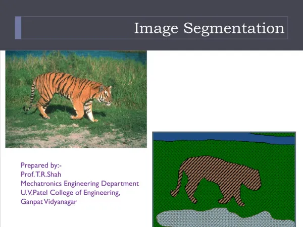
Interactive Image Segmentation
Interactive Image Segmentation. Image Segmentation Problem. Segmentation refers to the process of partitioning an image into multiple non-overlapping segments

Interactive Image Segmentation
E N D
Presentation Transcript
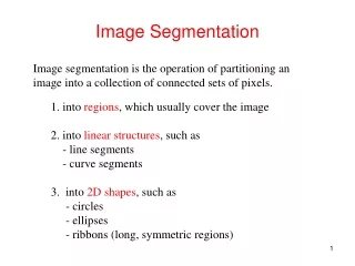
Image Segmentation Problem • Segmentation refers to the process of partitioning an image into multiple non-overlapping segments • The goal of segmentation is to simplify and/or change the representation of an image into something that is more meaningful and easier to use. • Image Segmentation is a traditional Computer Vision problem. However, it is also an ``unsolved’’ problem. • Problem of Automatic segmentation: • Different segmentation method favors different criterions • Different applications / human have their own different segmentation criterions • An universal segmentation algorithm does not exist
Interactive Image Segmentation • Different user has different preferences on segmentation • Why don’t we ask user to guide the segmentation process ? Interactive Image Segmentation • Goal is to provide an intelligent tool that minimize the amount of user’s works • Topics in this class • Image Snapping [Siggraph’95] • Intelligent Scissors [Siggraph’95] • Lazy Snapping [Siggraph’04] • Extra reading materials • Grabcut [Siggraph’04] • Paint Selection [Siggraph’09] • Video Snap Cut [Siggraph’09]
Image Snapping • SIGGRAPH, 1995 • Michael Gleicher, Apple Computer in 95, now Assoc. Prof. at U. Wisconsin • Idea Cursor snapping is a technique that helps a mouse “snap” to a widget • The cursor is the pointer device used in “direct manipulation” type of user interfaces (Windows is a direct manipulation interface) • In many graphics applications (esp CAD/CAM), the mouse will “snap” when it gets close to a button or object • This allows the user not to be so accurate Image snapping • Have the mouse cursor snap to image features • Same idea, you don’t have to be very precise
Image Snapping – figures from paper Snapped position Mouse position
Basic Idea ? User clicks on an image point. How do we find “feature” to snap to?
Basic Idea ? Naïve approach? Search in a “spiral” pattern, increasing in distance from the point, until “something” is found.
Problems with Naïve Approach • No method for rejecting noise • Needs a preset stopping criteria • No way to trade off certainty and size for distance • Stops at first feature it finds, a better feature may be equal distance away CAN WE DO BETTER?
Image Snapping Approach • Consider the “feature map” as a height-field • Follow the feature map gradient (1st derivation) from point position until we find a suitable feature Analogy: Point is a ball. Drop it and let it roll down the hill until it finds a stopping place. 1D example: Similar in idea to numerical “gradient decent” methods. http://mathworld.wolfram.com/MethodofSteepestDescent.html
Snapping Approach • Search follows gradient • Stopping criteria is where we can’t search in a downward direction anymore Sharp images can cause problems. Blur image to make gradients smooth.
Blurring Image First • Blurred image helps remove noise • We can blur at different amounts, this can help the level of detail we want to snap too blurred Input blurred more
Basic Algorithm • Input image -> feature map • Blur image -> apply sobel mask -> get gradient map • Finding a feature (snapping) • When mouse is clicked • Follow gradient path until we find a “minimum” • Minimum is where there is either no more gradients (constant region) • Or the gradients are very different (line) • If no minimum is found within a certain distance, stop search too (nothing to snap too)
Image Snapping • Gradient Map Click hereand followthe gradient. One problem is thatstopping position maybe between 2 pixels. (that is, not aligned on a pixel) Note that the original imagehas been blurred. 2-pixel black lineis now gray.
Alignment issues We can compute “sub-pixel” accurate snapping. Or we canforce the snapping to be on a pixel.
Sub-pixel Snapping Yellow line: Sub-pixel snapping Green line: what the userdraws
Adding Hysteresis • One problem is that the snapping has no “memory” of where it snapped last • If you are tracing, this can cause the cursor to jump around • A kind of “hysteresis” can be introduced that gives preference to the last feature snapped too Hysteresis def: “History dependence of a physical system”
Example With Hysteresis effect Without adding Hysteresis effect
How to Add Hysteresis? • The idea is to pull the snapped cursor instead of snap from the input cursor • Potential problem • If you pull the cursor too much, it may jump to the wrong place • If you pull too little, it will snap back to the starting place • Solution Initialize: Δp=1 Initial snapped cursor position (x,y) Step 1: Pull Δp-pixels towards the user-cursor if it snaps back to (x,y)? Δp=Δp+1 goto Step 1: else you have the new (x,y) position old position new position Δp move
Image Snapping Summary • Interesting idea aiding the user’s image manipulation • Reduces the level of accuracy • Aid in “tracing” objects (Hysteresis + snapping) • This is one of the early “Graphics meets Vision” paper • I recommend you read it, you’ll see how the author describes many of the vision terms • Now (more than 10 years later), SIGGRAPH readers are assumed to have a much better background in vision/image processing
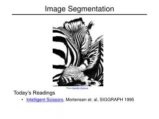
Intelligent Scissors • SIGGRAPH, 1995 • Eric Mortensen and William A. Barrett • Idea • Treat segmentation as a graph-search problem • Between two starting points (which dynamically change) • Find shortest path on the graph • Path edge costs are related to image content
Segmentation as a graph path problem B A • Treat entire image as a graph • Pixels are nodes, eight edges,e, between every pixels • Clicking on two points, you want to find theminimum cost path between A and B
Edge costs? Edge cost are based on the image content. In particular, gradient information (edge) Thresholded 2nd Derivate 1st Derivate magnitude (i.e. edge strength) Similarity of gradientdirection between twonodes
Pre-processing • Edge costs are pre-computed when the image is loaded • Requires 3x3 Laplacian and 2 3x3 Gradient (Sobel) filtering to be performed • Some additional calculations to compute the angle cost (see paper) Similar to the “Image Snapping”, authors mention blurring image first.
Shortest pathgraph algorithm. Note that this produces a spanning tree from the seed point s, to all nodes in the graph! Also see: http://en.wikipedia.org/wiki/Minimum_spanning_tree
Example of spanning tree expansion Initial input (with costs) Technically costs should be edges, not pixels First step of algorithm, all edge cost to theseed point are computed. [Note that diagonals arebeing waited by sqrt(2), thus 8 becomes 8*sqrt(2)=11] List L, now has 8 nodes on it (see algorithm) L = {1, 2, 4, 7, 7, 7, 11, 13} // these represent cost, but they are also linked back // to the pixel that they represent. (list is sorted!)
Example of spanning tree expansion Notice,these pixelschanged theircost. Its cheaperfor them to go thisway than diagonal (see first expansion). Their cost have tochange in list L too. Now all costs through“r” are computed. Recompute all costs. Minimum cost, place at the top of the list, letscall this “r”. Expansion 1: Remove lowest value, and expand by unvisited neighbors L = {1, 2, 4, 7, 7, 7, 11, 13} Expansion 2: L = {2, 4, 5, 6, 6, 7, 7,9,13,14} // new list afterwards. Look very // carefully
Next Several Expansion Next several expansions by “2”, “4”, “5” Final expansions. Note, we now have a path fromevery pixel back to the seed “s”.
Live Wire User clicksa seed point. - spanning tree is quickly calculated. Then moves the mouse to “free points”. The ‘wire’ magicallyfind the path basedon spanning tree.
Have you seen this before? Photoshop “magnetic lasso”
Some tricks for improvement • Hard to specify the initial seed point on the objects boundary • So, “snapping” is used to snap the first seed point • Periodically, a new seed point is automatically introduced (which re-computes the spanning tree). • This is called “cooling”
More tricks • Dynamic training (or feature cost adjustment) Adjust (normalize) all gradient close to the live-wire (in a local region) to strengthen them. This allows the wire to snap back to the face. Wire keeps snapping toman’s shoulder because it is darker (stronger gradient)
Some results (final output)
Intelligent Scissors Summary • Effective tool for object extraction • Combines real-time graph-search with user interactive (and updating) • Adopted by Photoshop (with variations I’m sure) • Is it better than Image Snapping? • Notice they were published at the same conference, same year.
Lazy-Snapping • SIGGRAPH, 2004 • Yin Li, Jian Sun, Chi-Keung Tang, Harry Shum • Idea: • Problem with Image-snapping and Intelligent Scissors? • You still need to trace the object • This takes time • Can we do better? • How about just supply very rough scribble to denote the background and foreground? (this is lazy) input output markup
Treat object extraction as a 2-class classification problem background foreground Each pixel in the image shouldbe labeled as either “background” or “foreground” Result
Training examples via markup B G R F B n F pixels m B pixels Result: Pixels along user-scribble provide“supervised” RGB training-data Blue = background (B), yellow = foreground (F)
Simple 1-NN Classifier B G R Given an unlabeled pixel, C(i). Decide whether is background or foreground. ? F B Compute new pixels RGB Euclideandistance (L2-norm) to all labeled B pixels, and all labeled F pixels. Select nearest from each.
Assigning a score • For each pixel, we can assign a score that this pixel is either foreground or background. We will use these scores to “minimize” a function, so the lower the score the more confident a pixel is to below to a class. Notation of the following equation: xi is a pixel label (not its color). 1=foreground, 0=background E1 is the score F, B represent the training-data (already labeled). U are unlabeled/uncertain pixels. Read carefully. Pixel that is already labeled as foreground hasa score of 0 for being foreground, infinite as being labeled background. Background pixels are defined similarly. Uncertain regions
Adding a Markov Random Field • The per-pixel score is not enough • To perform the final labeling, an MRF is used – this enforces spatial constraints MRF Nodes Cost for labeling a node is E1(xi) (as defined on the previous slide) Node cost often called the “data cost” or“likelihood energy” MRF Edges Edges have to vertices xi and xj. Cost for an edge depend on what labelsare assigned to xi and xj. We will call this cost E2(xi,xj) (defined on next slide) Edges cost often called “smoothness term”, or “smoothness prior”, or “prior energy” This is a graph, with {V,E} V = nodes (vertices) E = edges Excellent MRF code: http://vision.middlebury.edu/MRF/
Edge Costs where Possible Edge Configurations and cost: Configuration 3 Configuration 1 Configuration 2 B F B F F B Cost = 0 Cost = 0 1/[Color Difference] Small Color Difference = Large Cost Large Color Difference = Small Cost (Ask yourself why?) |1-1| = 0 |0-0| = 0
How Edge Cost work B ? F B ? F F B x11 x9 x10 Label with The value that results in the smallest cost For: E(x9,x10) and E(x10,x11) ? ? F F B If color differenceis large, then cost (B,F) = small If color difference is small, then Cost (B,F) = large
Solving MRF • Put all of these costs together and find the optimal labeling for the whole network B ? ? ? ? B ? ? Solution is the label set that minimizescost function E(X). Solution is often an approximation. Many approaches for solvingminimizing MRF E(X). ? ? ? F Remember, some points are already labeled (from markup), so they are fixed.
Speedup up the computation • Speed up? • First segment the image into larger regions • Use the “watershed algorithm” to pre-segment • Nodes are the centers of the watershed Labeling an MRF by each pixel is slow • Will not allow for interactive rates Here, each pixel is a V, and there are edges between all pixels Here, only the centers of the segmented regions are V, and theedges are the connection. Presumption is that the segmentationpreserves boundaries well.
Clean up • This classification using MRF is not perfect • Any mistakes can be corrected manually • Li et al introduce a “boundary editing” approach to help • It allows the user to draw the boundary, pixels re-labled near the boundary • Edge energy is modified to incorporate the drawn boundary • Only pixels within the “yellowish” region are processed • (See paper for more details, you should be able to understand it based on the notes)
Final Results Demo.
Lazy Snapping Summary • Scribble based segmentation • Very fast and intuitive • Avoids having to get too close to the edge • This scribble user interface have been used in many later applications • Extended to Video Snapping in next year Siggraph • A continue work of “Paint Selection” based on instant feedback and multi-core computation published in this year Siggraph
Summary • We’ve discussed some computer-aided/user-assisted approaches for interactive image segmentation • Combine computer-vision/image processing with user-assistance • Some people are calling this “Interactive Computer Vision” • Greatly helps the processing of photos