Download
1 / 28
280 likes | 300 Vues
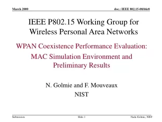
IEEE P802.15 Working Group for Wireless Personal Area Networks. WPAN Coexistence Performance Evaluation: MAC Simulation Environment and Preliminary Results N. Golmie and F. Mouveaux NIST. Outline. MAC coexistence evaluation platform Part I: Simulation Environment Traffic model MAC model

E N D
IEEE P802.15 Working Group for Wireless Personal Area Networks WPAN Coexistence Performance Evaluation: MAC Simulation Environment and Preliminary Results N. Golmie and F. Mouveaux NIST Nada Golmie, NIST
Outline • MAC coexistence evaluation platform • Part I: Simulation Environment • Traffic model • MAC model • PHY and RF assumptions • Part II: Preliminary Results • Sanity check • Bluetooth reference scenario: LAN Access Nada Golmie, NIST
MAC Coexistence Evaluation Platform • Explore different models for the MAC layer coexistence performance evaluation platform. • Invariant: performance results are collected at the MAC layer based on PHY, RF models and assumptions. Nada Golmie, NIST
MAC Coexistence: Model I • Heterogeneous set-up where BT and 802.11 are co-located within the same environment as proposed in [1]. Traffic Models Traffic Models BT MAC 802.11 MAC Network Topology in a Coexistence Environment PHY & RF Layer PHY & RF Layer Traffic Models Traffic Models 802.11 MAC BT MAC PHY & RF Layer PHY & RF Layer [1] IEEE 99/117 Nada Golmie, NIST
MAC Coexistence: Model II • Homogeneous set-up where different devices (BT or 802.11) are considered separately with respect to (accurate) interference models.* Traffic Models Traffic Models Interference Models based on experimental measurements, analysis BT MAC BT MAC PHY & RF Layer Assumptions PHY & RF Layer Assumptions * IEEE 802.15-99/98r0 Nada Golmie, NIST
Simulation Environment Nada Golmie, NIST
Traffic Models: LAN Access • LAN Access Profile, Bluetooth Spec. V1.0B • PPP connection with LAP in order to gain access to a LAN. LAN Access Point: Ethernet, Token Ring, Fiber Channel, Cable Modems, Firewire, Home Networking Data Terminal: Laptops, Notebooks, desktop PCs and PDAs TCP/UDP TCP/UDP IP PPP Networking IP PPP PPP RFCOMM RFCOMM ME LAN LAN L2CAP L2CAP BB BB Nada Golmie, NIST
Traffic Distribution: IP Packet Generation * IEEE 802.14/96-083r2 Nada Golmie, NIST
Packet Encapsulation IP IP Packet: Header + Payload 8 8 8 16 16 8 Protocol FLAG Address Control INFO = 0 -1500 bytes FCS FLAG PPP 8 8 8-16 8 RFCOMM Address Control Length INFO =ANY SIZE FCS 16 16 Channel ID PAYLOAD = 0 - 65535 bytes Length L2CAP Nada Golmie, NIST
Baseband Segmentation 16 16 L2CAP Channel ID PAYLOAD = 0 - 65535 bytes Length 2 1 9 4 16 2/3 DM3 L_CH Flow Length PAYLOAD= 0 - 121 bytes CRC FEC 2 1 9 4 16 2/3 DM5 L_CH Flow Length PAYLOAD= 0 - 224 bytes CRC FEC 72 54 Baseband Access Code Header PAYLOAD = 0 - 2745 bits Nada Golmie, NIST
MAC Model • Developed a BT MAC device in OPNET*. *OPNET is a Trademark of OPNET Technologies Inc. Nada Golmie, NIST
MAC Model Assumptions • Connection mode (no page scan or inquiry) • Master / Slave models • Round Robin master transmission scheduler • Asynchronous Connection Less (ACL) Link • Frequency Hopping Future Extensions • Synchronous Connection Oriented (SCO) Link • master scheduler • broadcast; L2CAP (?); LMP (?) Nada Golmie, NIST
TX Model Attributes* * OPNET Transmitter model attributes Nada Golmie, NIST
TX Parameters • Transmission+Propagation delay: computes the time required to transmit a packet until it reaches its destination. • Closure: determines if a signal can reach a destination and allows dynamic enabling and disabling of links. • Channel match: classifies the transmission as valid, noise, ignore based on frequency, bandwidth, data rate, spreading code etc. • Transmitter antenna gain: computes transmitter antenna gain in the direction of the receiver. Nada Golmie, NIST
RX Model Attributes* * OPNET Receiver model attributes Nada Golmie, NIST
RX Parameters • Noise figure:effect of thermal noise on radio transmission. • Ecc threshold/model: Percentage of bit errors allowed in a packet (err/bit). • Power model: computes the received power level for an incoming transmission. • Background noise/ Inoise: computes the background/ interference noise affecting incoming radio transmissions. • SNR/ber models: computes signal-to-noise ratio and expected bit error rates. Nada Golmie, NIST
RX Statistics • BER: bit error rate for the packet arriving at the receiving channel. • Packet loss ratio: boolean value corresponding to the acceptance/rejection of packets. • Power: average power of packet arriving at the receiver channel. • Signal/noise ratio: ratio of the average power of a packet received and the combined average power of interference sources. Nada Golmie, NIST
Channel Attributes* * OPNET Channel attributes Nada Golmie, NIST
Preliminary Results Nada Golmie, NIST
Sanity Check • Number of devices in a piconet: 2 devices (Master/ Slave). • Distance between devices: 10m • Traffic: DM5 packets symmetric master/slave communication, exponential distribution for packet interarrival rate. • Baseband packet size is: 72 + 54 + (224 + 2 + 2) * 8 + FEC = 2871 bits Access Header payload DM5 HeaderCRC 6 + 915 Nada Golmie, NIST
Sanity Check (cont.) • Maximum bit rate per device (including headers, CRC, FEC overhead) is: 2871/(5 * 625 * 2) = 0.45936 Mbits/s • Minimum access delay (master) at low offered load (no packet waiting in buffer) is: 5 (slots) * 625 (us) = 3.125 ms • Maximum access delay (master) at low offered load (no packet waiting in buffer) is: 15 (slots) * 625 (us) = 9.375 ms Nada Golmie, NIST
Sanity Check Results: Throughput Nada Golmie, NIST
Sanity Check Results:Access Delay * ** Note: ** Access delays are collected at the slave corresponding to the master traffic access delay. ** Offered load is a percentage of the total channel capacity in both directions Nada Golmie, NIST
LAN Access Scenario • Number of devices in a piconet: 2 devices (Master/ Slave). • Distance between devices: 10m • Traffic: LAN Access (IP traffic distribution) • Average packet size is: 385.1 bytes 1 DM5 (224 bytes) + 1 DM5 (162 bytes) = 4992 bits • Maximum bit rate per device (including headers, CRC, FEC overhead) is: 4992/(10 * 625 * 2) = 0.39936 Mbits/s Nada Golmie, NIST
LAN Access Results: Throughput Nada Golmie, NIST
LAN Access Results:Access Delay * ** Note: ** Access delays are collected at the slave corresponding to the master traffic access delay. ** Offered load is a percentage of the total channel capacity in both directions Nada Golmie, NIST
Summary • Presented a status report on the BT MAC model development. • Preliminary results: • sanity check • BT reference scenario Nada Golmie, NIST
Next Step • Results: • WLAN reference scenario • Heterogeneous scenario with 2 WLAN devices and 2 BT devices. • Continue the development of the BT MAC model. • Extend the PHY and RF models • Several scenarios to look at with different traffic types, number of devices, configurations. Nada Golmie, NIST