
MACHINE DRAWING
E N D
Presentation Transcript
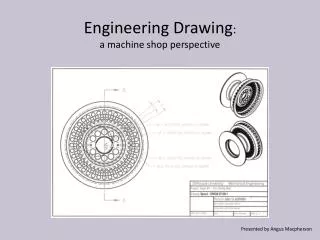
MACHINEDRAWING Presented by GUNTLA SANDEEP KUMAR M.Tech, Assistant Professor DEPARTMENT OF AUTOMOBILEENGINEERING VISAKHA INSTITUTE OF ENGINEERING & TECHNOLOGY
SYLLABUS SectionA Introduction graphic language, classification of drawing,principle of drawing, IS codes for machine drawing, lines, scales, section dimensioning, standard abbreviation, – Limits , fits and Tolerance ( Dimensional and Geometrical tolerance ) , Surfacefinish, Gears : Gear terminology, I.S. convention representation of assembly of spur gears, helical gears, bevel gears , wormand wormwheel. SectionB Orthographic projections: principle of first and third angle projection, orthographic views from isometric views ofmachine parts /components. Drawing of sectional views:- Coupling, Crankshaft, Pulley, Piston and Connecting rod, Cotter and Knuckle joint. Riveted Joint and WeldedJoint.
SYLLABUS Free hand sketching: Need for free hand sketching ofstandard parts and simple machinescomponents. SectionC Assembly drawing with sectioning and bill of materials from given detailed drawings of assemblies: Lathe Tail stock, Machine vice, Pedestalbearing SectionD Assembly drawing with sectioning and bill of materials from given detailed drawings of assemblies Steam stop valve, Stuffing box, Drill jigs and Millingfixture.
Introduction- GraphicLanguage • Engineering drawing has its origin sometime in500 BC in the regime of King Pharos of Egypt when symbols were used to convey the ideas among people. • Irrespective of language barriers, the drawings can be effectively used in other countries, in addition to the country where they areprepared. • Thus, the engineering drawing is the universal language of allengineers.
Classification ofDrawing • MachineDrawing- • Pertaining tomachine parts orcomponents. • presented througha number of orthographicviews. • Size & shape of component isfully understood.
Production Drawing– • Referred as workingdrawing. • Should furnish all dimensions, limits & special finishingprocesses • such as heat treatment, honing, lapping, surface finish,etc. • Title should also mention the material used for the product,number • of partsrequired.
PartDrawing- • Detailed drawing of a component to facilitateits manufacture. • Follows principles of orthographicprojection • Assembly Drawing- • - A drawing that shows the various parts of amachine in their correct working locations.
Principle ofDrawing • To provide the correct information about drawings to all concerned people, the drawing must be prepared,following certain standard practices, as recommended by Bureau of Indian Standards(BIS). • Sheet Size- For a reference sizeA0 having a surface area of1 • X = 841 mm and Y = 1189mm.
Title Block– • Title of thedrawing • Sheetnumber • Scale • Symbol, denoting the method ofprojection • Name of the firm /institute • Initials of staff drawn, checked andapproved.
Borders & Frames– • Minimum 20 mm for size A0 & A1. Minimum 10 mm for size A2, A3,A4. • CenteringMarks • Metricreference graduation • Gridreference system • Trimmingmark
Scales • The various types of scales used in machine drawingare • Fullscale 1:1 • Reducedscale 1:X • Enlargedscale X:1 • The standard scales are given inTable
Dimensioning As far as possible, dimensions should be placed outsidethe view. Should be taken from visible outlines, not from hiddenlines. Dimensioning to a centre line should be avoided except when the centre line passes through the centre of ahole. Each feature should be dimensioned only once in adrawing. Placed on the view or section that relates most clearly tothe correspondingfeatures. Each drawing should use the same unit for alldimensions, but without showing unitsymbol. Minimum dimensions should be placed to define awhole part. No features of a part should be defined by more thanone dimension in any onedirection.
Elements ofDimensioning Dimension line — It is a thin continuous line terminated byarrowheads touching the outlines, extension lines or centrelines. Extension line (Projection line) — It is a thin line drawn outside and along the outline. There should be a gap of about 1 mm between the extension line and theoutline. Leader line —One end of the leader terminates either in an arrowhead or a dot. The arrowhead touches the outline, while the dot is placed within the outline of the object. The other end of the leader is terminated at a horizontalline Arrowhead — An arrowhead is placed at each end of a dimension line. Its pointed end touches an outline, an extension line or a centre line. The length of arrowhead should be about three times its maximum width. The triangle of the arrow should be completely filledin.
Methods of indicatingDimensions Aligned system,and Unidirectionalsystem. Aligned system — In the aligned system, the dimensions are placed above the dimension lines and may be read either from the bottom or from the right side of thedrawing Unidirectional system — In the unidirectional system, all dimensions are placed with respect to the bottom of the drawing, irrespective of the disposition of the dimension line. In the system, the dimension lines are broken to insert their dimensions . This system is preferred for big drawings specially when it is not convenient to read the dimension from the right side or any otherdirection.
Limits , Fits andTolerance • The system in which a variation in dimensions is acceptedis called the limitsystem. • The allowable deviations are calledtolerances. • The relationships between the mating parts are calledfits.
Limits • The two extreme permissible sizes between which theactual • size is contained are calledlimits. • The maximum size is called the upper limit and theminimum • size is called the lowerlimit. • Tolerances • Tolerance is denoted by two symbols, a letter symbol anda number symbol, called thegrade. • It is the difference between lower and upperdeviation.
Types ofFits 1. Clearance Fit– It is a fit that gives a clearance between the two mating parts.
Types ofFits 2. Transition Fit– This fit may result in either an interference or aclearance, depending upon the actual values of the tolerance of individualparts.
Types ofFits 3. Interference Fit- If the difference between the hole and shaft sizes isnegative before assembly; an interference fit isobtained.
Surfacefinish The geometrical characteristics of a surfaceinclude, Macro-deviations, Surface waviness,and Micro-irregularities. The surface roughness is evaluated by the height, Rt and meanroughness index Ra of themicro-irregularities.
Gears • Gears are machine elements, which are used for power transmission between shafts, separated by smalldistance. • While two gears are meshing, the teeth of one gear enter the spaces of the other. Thus, the drive is positive and when one gear rotates, the other also rotates; transmitting power from one shaft to theother.
Pitch Circle – Outlines of imaginary smooth rollers orfiction discs in every pair of matinggears. • Pitch Diameter – Diameter of pitch circle(P.C.D.) • Root Diameter – Diameter at the bottom of toothspace. • Addendum – Height from pitch circle to the tip of thetooth. • Dedendum – Depth of tooth space below pitchcircle. (addendum +clearance) • Circular Pitch (C.P.) – Length of arc of pitch circle between similar faces of successiveteeth. • Diametral Pitch (D.P.) – Number of teeth divided by pitch diameter. • Module (m)- Pitch diameter divided by number ofteeth. • Circular Tooth Thickness – Length of arc of the pitch circle between opposite faces of same tooth (0.5C.P.)
Base Circle Diameter – Diameter of circle fromwhich involute isgenerated. • Line of Action – Common tangent to the two basecircles, which passes through the pitch point of a pair of mating gears. • Pressure Angle- Acute angle formed between the lineof action and common tangent to the two pitch circles,which passes through the pitchpoint. • Tooth Fillet – Rounded corner at the bottom of toothspace. • Centre Distance – Distance between centers of a pair of mating gears and is equal to sum of the radii of pitch circlesof the twogears. • Pitch Point – Point of contact between the pitch circlesof • two gears in mesh & lies on the line joining theircenters.
Toothface • Toothflank • Crest oftooth • Root oftooth • Wholedepth • Workingdepth • Addendumcircle • Dedendum / rootcircle • Chordalpitch
GearCalculation • Circular Pitch = Circumference of P.C.D. / No. ofteeth • = P.C.D.xπ / No. ofteeth • C.P. = P.C.D.xπ /N • Diametral Pitch = No. of teeth / Pitch CircleDiameter • = N /P.C.D. • C.P.xD.P. =π • C.P. = π/D.P. And D.P. = π /C.P. • Metric Module , m = Pitch Circle Diameter / No. ofteeth • = P.C.D. /N • = 1 /D.P. • C.P. = π/D.P. = π xm
GearCalculation Outside Diameter = Pitch diameter +2xAddendum Root Diameter = Pitch diameter - 2xDedendum Clearance = Dedendum –Addendum Tooth thickness = C.P. / 2 Addendum = 1 / D.P. = C.P. /π =m Clearance = C.P. / 20 = (π/D.P.) x (1/20) = 0.157 xm Pressureangle, θ = 14.5 or 20degree Base circle diameter, B.C.D. = P.C.D. x Cosθ Involute gears will work correctly together if they have thesame pressure angle and diametralpitch.