Download

1 / 41
410 likes | 436 Vues
Explore sensor signals for position, velocity, and acceleration using strain gauge, magnetic coil, and accelerometer in an advanced ENGR-4300 project. Learn to build and calibrate circuits, measure beam dynamics, and analyze outcome data effectively.

E N D
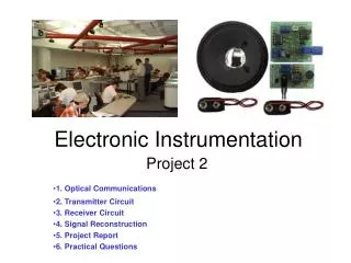
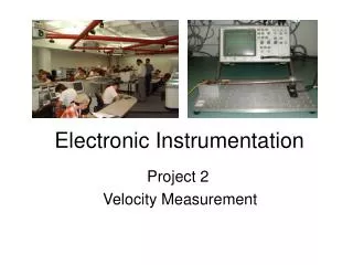
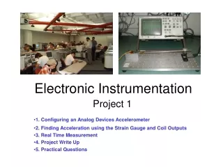
Electronic Instrumentation Project 2 Acceleration Measurement
Cantilever Beam Sensors • Position Measurement – obtained from the strain gauge • Velocity Measurement – obtained from the magnetic pickup coil • Acceleration Measurement – obtained from the Analog Devices accelerometer ENGR-4300 Electronic Instrumentation
Sensor Signals • The 3 signals • Position • Velocity • Acceleration 2 of the 3 plots must be scaled to see them on the same figure. ENGR-4300 Electronic Instrumentation
Basic Steps for Project • Build the accelerometer circuit • Mount it close to the end of the beam • Build amplified bridge circuit • Calibrate the sensors • Measure position, velocity and acceleration, 2 channels at a time • Determine the mathematical representations for x, v, and a. • Demonstrate that all 3 signals can be used to find the acceleration of the beam. ENGR-4300 Electronic Instrumentation
Building the Accelerometer Circuit ENGR-4300 Electronic Instrumentation
The Analog Device Accelerometer • The AD Accelerometer is an excellent example of a MEMS device in which a large number of very, very small cantilever beams are used to measure acceleration. A simplified view of a beam is shown here. ENGR-4300 Electronic Instrumentation
Accelerometer Circuit • The AD chip produces a signal proportional to acceleration • The Op Amp amplifies the signal MAX473 Op Amp Circuit Accelerometer Chip ENGR-4300 Electronic Instrumentation
Accelerometer Circuit • The ADXL150 is surface mounted, so we must use a surfboard to connect it to a protoboard ENGR-4300 Electronic Instrumentation
Improved Op Amp • We use a Maxim 473 Op Amp to improve performance • This device requires only ground and 5V (rail voltages) • The output can scan from rail-to-rail ENGR-4300 Electronic Instrumentation
Part Costs • Maxim MAX-473 Single Supply 10MHz Op Amp ($3.58 from Digi-Key) • Compare with LM741 Dual Supply Op Amp ($0.22 from Electronix Express) • Analog ADXL150 Accelerometer $13.70 • Note that these are all single part costs. ENGR-4300 Electronic Instrumentation
Caution • Please be very careful with the accelerometers. While they can stand quite large g forces, they are electrically fragile. If you apply the wrong voltages to them, they will be ruined. AD is generous with these devices (you can obtain samples too), but we receive a limited number each year. ENGR-4300 Electronic Instrumentation
Extra Protoboard • You will be given a small protoboard on which you will construct your accelerometer circuit. • Keep your circuit intact until you complete the project. • Return the accelerometer surfboard at the end of each class ENGR-4300 Electronic Instrumentation
Mounting the Accelerometer ENGR-4300 Electronic Instrumentation
Mount the Accelerometer Near the End of the Beam • Place the small protoboard as close to the magnetic sensor as possible • The axis of the accelerometer needs to be vertical ENGR-4300 Electronic Instrumentation
Accelerometer Signal • The output from the accelerometer circuit is - per g, where g is the acceleration of gravity and -Rf /Ri is the gain of the Op Amp circuit. Gain is negative. • In the equations below, the units are in [ ] ENGR-4300 Electronic Instrumentation
Calibrate the Position and Velocity Sensors ENGR-4300 Electronic Instrumentation
Amplified Strain Gauge Circuit 741 ENGR-4300 Electronic Instrumentation
Position Measurement Using the Strain Gauge • Set up the amplified strain gauge circuit • Place a ruler near the end of the beam • Make several measurements of bridge output voltage and beam position • Find a simple linear relationship between voltage and beam position (m) in meters/V. ENGR-4300 Electronic Instrumentation
Velocity Measurement Using the Magnetic Pickup Coil • From Maxwell’s Equations, the voltage induced in a coil due to a moving magnetic field is given by where v is velocity, B is magnetic field, N is the number of turns in the coil, and A is the area of the coil. Simplifying ENGR-4300 Electronic Instrumentation
Velocity Measurement • For small deflections, the change in the magnetic field with position is roughly constant, so the voltage is proportional to the beam velocity. • For large deflections, you should notice that the voltage will not look like a decaying sinusoid ENGR-4300 Electronic Instrumentation
Velocity Measurement • There is no simple direct way to calibrate the velocity measurement • However, it can be calibrated by comparing it to the position measurement • To facilitate this comparison, we find a ratio that relates the amplitude of the coil to the amplitude of the amplified strain gauge ENGR-4300 Electronic Instrumentation
Comparison of x and v signals • Recall the coil and amplified strain gauge signals should be out of phase by 90 degrees • We want the amplitude of the two signals to be about the same • If RA is not close to 1, change the gain of the differential amplifier • Use a Lissajous pattern to show the ratio of the two amplitudes (circle) • You must use the same voltage scales for both ‘scope channels for this comparison to be valid ENGR-4300 Electronic Instrumentation
Calibrating the Velocity Measurement • Note, all measurements of position and velocity must be taken with the accelerometer board installed so that the same conditions hold for all measurements • Measure the strain gauge and coil outputs simultaneously • Capture these signals using Agilent Intuilink • Determine RA ENGR-4300 Electronic Instrumentation
Calibrating the Velocity Measurement • The x and v signals are decaying sinusoids. • We know the calibration for x • And we know that • Using the ratio of the two amplitudes Asg=RAAcoil ENGR-4300 Electronic Instrumentation
Acceleration • When both x and v are calibrated, it is possible to find the acceleration a(t) by taking derivatives of these expressions • Record the accelerometer signal at the same time as the coil, use the calibration factors you have found to adjust both signals, take the derivative of the coil signal, average the accelerometer signal, and compare the two resulting curves. • Record the accelerometer signal at the same time as the strain gauge, use the calibration factors you have found to adjust both signals, take the second derivative of the strain gauge signal, average the accelerometer signal and compare the two resulting curves. ENGR-4300 Electronic Instrumentation
Data Analysis • Take derivatives with the SLOPE function in Excel • The strain gauge signal (converted to meters) must be differentiated twice to find acceleration. • The coil signal (converted to meters/second) must be differentiated once to find acceleration. • Because it uses regression, the SLOPE function will introduce a phase shift proportional to the number of points in the regression. • Use the AVERAGE function on the accelerometer signal • The accelerometer signal must be averaged over the same number of points that you used in the regression for the SLOPE function. ENGR-4300 Electronic Instrumentation
The SLOPE Function(for use on coil and strain gauge signal) • Given an array of points with x in A1:An and y in B1:Bn • Regression over 10 points: In cell C1, put the formula =SLOPE(B1:B9,A1:A9) • Now copy this formula in the rest of C. • Graph the data to compare ENGR-4300 Electronic Instrumentation
The AVERAGE Function(for use on accelerometer signal) • Given an array of points with x in A1:An and y in B1:Bn • For averaging over 10 points: In cell C1, put the formula =AVERAGE(B1:B9) • Now copy this formula in the rest of C. • Graph the data to compare ENGR-4300 Electronic Instrumentation
Some Questions • How would you use some of the accelerometer signals in your car to enhance your driving experience? • If there are so many accelerometers in present day cars, why is acceleration not displayed for the driver? (If you find a car with one, let us know.) • If you had a portable accelerometer, what would you do with it? ENGR-4300 Electronic Instrumentation
Project Report • Introduction • Purpose of project • 2 topics • Background • Basic theory • How the circuits work • Calibration process ENGR-4300 Electronic Instrumentation
Project Report • Initial Design • Building and calibrating the accelerometer circuit. • Finding strain gauge and coil amplitude ratio. • Calibrating position and velocity measurements • Taking initial data • Final Design • Compare acc. from strain gauge and accelerometer • Compare acc. from coil and accelerometer ENGR-4300 Electronic Instrumentation
Project Report • Conclusions • How does your data compare? • Sources of error • Questions • Discuss extra credit • Personal Responsibilities • Appendices • Extra Credit Details ENGR-4300 Electronic Instrumentation
Extra Credit • Really good results • Strain gauge, coil, and accelerometer signals all on same plot • Velocity comparison in Excel • Build a differentiator • Calibrate the ADXL150 ENGR-4300 Electronic Instrumentation
Passive Differentiator ENGR-4300 Electronic Instrumentation
Active Differentiator ENGR-4300 Electronic Instrumentation
Typical Acceleration • Compare your results with typical acceleration values you can experience. ENGR-4300 Electronic Instrumentation
Crash Test Data • Head on crash at 56.6 mph Ballpark Calc: 56.6mph = 25.3m/s Stopping in 0.1 s Acceleration is about -253 m/s2 = -25.8 g ENGR-4300 Electronic Instrumentation
Crash Test Data • Head on crash at 112.1 mph Ballpark Calc: 112.1mph = 50.1 m/s Stopping in 0.1 s Acceleration is about -501 m/s2 = -51.1 g ENGR-4300 Electronic Instrumentation
Crash Test Analysis Software • Software can be downloaded from NHTSA website • http://www-nrd.nhtsa.dot.gov/software/load-cell-analysis/index.htm ENGR-4300 Electronic Instrumentation
Crash Videos • http://www.sph.emory.edu/CIC/CLIPS/mvcrash.html • http://www.arasvo.com/crown_victoria/cv_movies.htm ENGR-4300 Electronic Instrumentation
Airbags • Several types of accelerometers are used & at least 2 must sense excessive acceleration to trigger the airbag. ENGR-4300 Electronic Instrumentation