Siemens NeSSI Update & Activities Summary
Explore Siemens' approach and activities for NeSSI, focusing on requirements, benefits, and advancements in smart sampling systems.

Siemens NeSSI Update & Activities Summary
E N D
Presentation Transcript
NeSSI Update Siemens Activities CPAC; NeSSI: May 2006
Topics • Summary of Siemens activities • Review of requirements • More detail on Siemens approach
Action and Inaction – Benefits and None • The NeSSI concept is intended to bring benefits to users by doing a common thing better • Reduced cost • Size, utilities, material, labor • Higher availability • Intrinsic reliability, MTBF, MTTR, skill set, parts • Better performance • Volumes, flow paths, design • On any project intended to result in the benefits of doing a thing better: • The costs continue to occur even if you do nothing; • The benefits NEVER occur if you do nothing! • Sometimes, you need to do something – maybe ANYTHING – even if it’s not perfect – in order to get things going. • This can be true EVEN if you’re dealing with possible rework later on.
Summary of Siemens Activities • Working with a major user to meet the requirements of a specific large analyzer project • Strong time lines and “field-proven” requirements • Committed to development of a Generation 2 approach to “smart sampling system” design • Use of Generation 1 mechanical components and design • Development of Generation 2, intrinsically safe serial bus for component interconnection • Implementation of Generation 2 SAM functionality; both virtual and physical • Creation of a Sampling-System-specific human interface • Working cooperatively with 3 major substrate and component vendors to interface components to the Generation 2 bus • Continuing to work actively with NeSSI work groups on review and establishment of broader standards
Requirements Review • The NeSSI Vision • The needs of a practical sampling system • Some details
Air Power Air Power Air Power Air Power Process Process Dumb Analyzer Smart Analyzer HMI HMI The Analyzer System Today System Communication Network
Power Air Power Air Power Air Power Air Process Process Dumb Analyzer Smart Analyzer HMI SAM SAM HMI HMI The NeSSI Vision System Communication Network
Pieces Of the NeSSI Idea • New mechanical components • Modular • Standardized mounting platform • Interchangeable function • New electrical interconnection • Serial connection – plug in • Intrinsically safe • Self-identifying components • New smart design features (SAM) • Helpful HMI • Programmability • Standardized, transportable user programming
Requirements • Certain key requirements • Bus length • Active device count • Power consumption and distribution issues • Operational issues • Field repair and replacement considerations • Component identification issues • Support for interchangeability • Other requirements
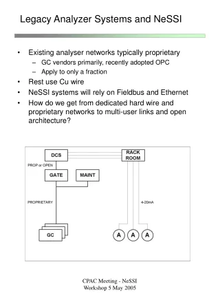
Bus Length • An “obvious” statement:Sampling systems are associated with analyzers • Bus length is the amount of cable required to go from a SAM to the sampling system and to continue linking to each of the components in the system • So, the key question is, where is the SAM relative to the sampling system?
Local Sample Conditioning • Summary • Sample is extracted from process and transported to the sampling system with only minimal modification • A relatively small portion of sample is cleaned and conditioned and provided to the analyzer • Distance between the analyzer and the sampling system is limited by sample transport considerations • Most typical situation that we think of and experience in the field – for both “smart” and “dumb” analyzers • Typically – a few feet; a reasonable maximum 10-20 meters Analyzer House 10’s to 100’s m SS Ax Analyzer (and SAM) Sample Conditioning System SS Ax 1 to 20 m
SAM System Network Close coupled; 1 meter Remote sample conditioning • Summary • Sample is extracted from the process and immediately cleaned and conditioned • Relatively small quantities of conditioned sample are transported to the analyzer • Distance between the analyzer and sample conditioning system is limited by transport considerations • Not (today) a common configuration. However, some systems have some remote devices • SAM associated with the system might be located adjacent to it 10’s to 100’s m Remote Sample Conditioning System Sample Delivery Analyzer (and SAM)
In situ analysis • Sample is not removed from the process • No sample conditioning exists
Component Count • How many active devices must be supported by the NeSSI bus? • There are differences between older, conventional construction techniques and NeSSI construction techniques. In NeSSI, the count will be larger!
Reference Sampling System Diagram1 stream plus auto-calibrate Analyzer Bypass Flow Analyzer Flow F Filter Drain Stream Select Valves Sample Flow Vent
Device Count Analyzer Flow Bypass Flow Filters Stream Select Flow / Pressure Adjust
Device Count • Per Stream (5 devices) • Stream select solenoid • Bypass flow / pressure adjust • Analyzer flow / pressure adjust • Filter pressure drop sense (1 or 2) • Per System • Temperature control / sense • Pressure / air sense • Number of streams • Minimum 1 • Typical 2-4 • Common 4-5 • Maximum 30 • Number of devices • Up to 200
Device Power and Connection Issues • Intrinsically safe systems • I.S. communication bus • I.S. device Power Source • Small devices • Connector space • Separation space for I.S. requirements • Power source • Preferred: power for communication and device have common source • Required: power be sourced through I.S.
Operational Issues • Repair and replacement must be “in place”. Positive device identification and physical placement must be provided • Address strapping in hardware • Address encoding before installation • Field repair needs to be supported under live power • Systems are not ad hoc. An analyzer is controlling the system and it’s needs and programming do not change • Device recognition during application engineering phases may be useful • Interchangeability requires that the system be able to confirm that a replacement device is of comparable type to device being replaced
NeSSI BusSystem Support Requirements • Up to 30 process streams in a sampling system plus 2 calibration streams. • Up to 200 active devices in a NeSSI Sampling System. (Additional “non-active” devices as needed) • Up to 1/2 of the active devices may be of any one type (example, pressure sense”) • Capability for support of standard functions: • pressure, temperature, flow monitoring (absolute measurement and/or binary alarm level) • pressure and flow absolute control • temperature control of substrate, sample cabinet, flowing stream fluid • automatic valve control to switch on / off or to divert process streams (block or 3-way) • Capability for the standard functions to be implemented in a variety of ways • All components should be interconnected on as few instances of the NeSSI bus as possible for cost reasons. If more than one instance is required, both shall be capable of being seamlessly controlled by a single analyzer or controller (PLC) operating as a NeSSI “SAM”.
System Bus Requirements (continued) • Analyzer may be mounted up to 10 meters away from sampling system • Opportunity for large number of component manufacturers to participate with large number of component types per manufacturer. • Sampling System HMI / visualization tool shall be capable of identifying an installed component type, manufacturer and model number for purposes of facilitating maintenance or replacement • Any single physical device should be able to represent itself using as multiple device types. • Interruptible while live – user can replace components while system is still operating • Intrinsically Safe for installation in Zone 1 (Type Ib) ; Division 1 • Must support power loading and control of power permitted by I.S. bus Start-up, minimum, maximum, abnormal, other power-management issues
Component Specs RequiredEntity Parameters • Power profile (for power budgeting) • Start up • Maximum • Steady State • Minimum • Stored power potential contributed to the system • Capacitive, inductive and resistive loading on the IS system • Active Load • Passive Load
Siemens Approach • Utilize existing device bus and protocol • Utilize available commercial methods to achieve I.S. compatibility and establish bus robustness • Provide bus interface method with software to interested component (device) suppliers and support for component interface design • Provide simple method of interface to the bus for other non-Siemens controllers
Siemens Implementation of NeSSI Bus Bus Access Controller Chip (chip spec and burn image by Siemens; assembly by component manufacturer) Siemens GC I.S. Power Supply Component interface electronics (by component manufacturer) Bus buffer Intrinsically Safe NeSSI Bus I.S. Barrier Mechanical component (by others)
s Maxum edition II Project Implementation WinCC Visualization WinCC Visualization Bridge module Modbus link
Future Plans and the Future Standard • Siemens is planning to implement a large scale NeSSI Generation 2 system using available technology • Other existing buses may still evolve into the long term standard for NeSSI • Fieldbus / Profibus • CAN Open • Other • Siemens plans to participate actively in development of standards for the NeSSI bus
Conclusions • Users should implement now • Use “closest available” from their preferred supplier • Be sure “closest available” is in the same direction as NeSSI is going • Don’t worry if “closest available” does not exactly match in the future • Plan to field retrofit IF desirable and needed • Siemens • Plans to support this approach using our available busses now • Plans to continue to support the NeSSI efforts toward full standardization