What Do We Know?
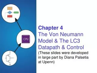
Chapter 4 The Von Neumann Model & The LC3 Datapath & Control (These slides were developed in large part by Diana Palsetia at Upenn ). What Do We Know?. Already discovered: Gates (AND, OR..) Combinational logic circuits (decoders, mux) Memory (latches, flip-flops)

What Do We Know?
E N D
Presentation Transcript
Chapter 4The Von Neumann Model & The LC3 Datapath & Control(These slides were developed in large part by Diana Palsetiaat Upenn)
What Do We Know? • Already discovered: • Gates (AND, OR..) • Combinational logic circuits (decoders, mux) • Memory (latches, flip-flops) • Sequential logic circuits (state machines) • Simple processors (programmable traffic sign) • What’s next? • Apply all this to build a working processor
MEMORY MAR MDR PROCESSING UNIT ALU TEMP CONTROL UNIT PC IR Von Neumann Model INPUT Keyboard Mouse Scanner Disk OUTPUT Monitor Printer LED Disk
CONTROL UNIT LC-3 Processor Von Nuemann Model
CONTROL UNIT LC-3 Data Path The data path of a computer is all the logic used to process information • Filled arrow • = info to be processed. • Unfilled arrow = control signal.
One More Device • Tri-state buffer • NOT an inverter! • Device with a special output that can take a third state (i.e. besides 0 and 1) • Allows wires to be “shared” • Alternative to mux • Only one source may drive at a time! • Usually used to control data over a bus D Q E Z = “high impedance” state
Data Path Components • Global bus • Set of wires that carry 16-bit signals to many components • Inputs to bus are controlled by triangle structure called tri-state devices • Place signal on bus when enabled • Only one (16-bit) signal should be enabled at a time • Control unit decides which signal “drives” the bus • Any number of components can read bus • Register only captures bus data if write-enabled by the control unit • Memory and I/O • Control signals and data registers for memory and I/O devices • Memory: MAR, MDR (also control signal for read/write) • Input (keyboard): KBSR, KBDR • Output (text display): DSR, DDR
• • • Memory • 2k x m array of stored bits • Address • unique (k-bit) identifier of location • Contents • m-bit value stored in location • Basic Operations: • LOAD • read a value from a memory location • STORE • write a value to a memory location 0000 0001 0010 0011 0100 0101 0110 1101 1110 1111 00101101 10100010
Data Path Components (cont.) • ALU • Input: register file or sign-extended bits from IR (immediate field) • Output: bus; used by… • Condition code registers • Register file • Memory and I/O registers • Register File • Two read addresses, one write address (3 bits each) • Input: 16 bits from bus • Result of ALU operation or memory (or I/O) read • Outputs: two 16-bit • Used by ALU, PC, memory address • Data for store instructions passes through ALU
ALU • Combinational Logic
Register File • A bank of (nearby) memory
Data Path Components (contd..) • PC and PCMUX • Three inputs to PC, controlled by PCMUX • Current PC plus 1 (normal operation) • Adder output (BR, JMP, …) • Bus (TRAP) MAR and MARMUX • Some inputs to MAR, controlled by MARMUX • Zero-extended IR[7:0] (used for TRAP; more later) • Adder output (LD, ST, …)
Data Path Components (cont..) • Condition Code Logic • Looks at value (from ALU) on bus and generates N, Z, P signals • N,Z,P Registers are set only when control unit enables them • Control Unit • For each stage in instruction processing decides: • Who drives the bus? • Which registers are write enabled? • Which operation should ALU perform? Lets Look at Instruction Processing next..
Instructions • Fundamental unit of work • Constituents • Opcode: operation to be performed • Operands: data/locations to be used for operation • Encoded as a sequence of bits (just like data!) • Sometimes have a fixed length (e.g., 16 or 32 bits) • Atomic: operation is either executed completely, or not at all
Example: LC-3 ADD Instruction • LC-3 has 16-bit instructions. • Each instruction has a four-bit opcode, bits [15:12]. • LC-3 has eight registers (R0-R7) for temporary storage. • Sources and destination of ADD are registers. “Add the contents of R2 to the contents of R6,and store the result in R6.”
Instruction Set Architecture • ISA = All of the programmer-visible components and operations of the computer • memory organization • address space -- how may locations can be addressed? • addressability -- how many bits per location? • register set • how many? what size? how are they used? • instruction set • opcodes • data types • addressing modes • ISA provides all information needed for someone that wants towrite a program in machine language(or translate from a high-level language to machine language).
FETCH instruction from mem. DECODE instruction EVALUATE ADDRESS FETCH OPERANDS EXECUTE operation STORE result Instruction Processing
Instruction Processing: FETCH • Idea • Put next instruction in IR & increment PC • Steps • Load contents of PC into MAR • Increment PC • Send “read” signal to memory • Read contents of MDR, store in IR F D EA OP EX S
CONTROL UNIT FETCH in LC-3 Control Load PC into MAR (inc PC) Data
CONTROL UNIT FETCH in LC-3 Control Load PC into MAR Data Read Memory
CONTROL UNIT FETCH in LC-3 Control Load PC into MAR Data Read Memory Copy MDR into IR
Instruction Processing: DECODE • Identify opcode • In LC-3, always first four bits of instruction • 4-to-16 decoder asserts control line correspondingto desired opcode • Identify operands from the remaining bits • Depends on opcodee.g., for LDR, last six bits give offsete.g., for ADD, last three bits name source operand #2 F D EA OP EX S
CONTROL UNIT DECODE in LC-3 Decoding usually a part of the Control Unit but can be seperate
Control Unit State Diagram • The control unit is a state machine. Here is part of asimplified state diagram for the LC-3: A more complete state diagram is in Appendix C. It will be more understandable after Chapter 5.
Instruction Processing: EVALUATE ADDRESS • Compute address • For loads and stores • For control-flow instructions • Examples • Add offset to base register (as in LDR) • Add offset to PC (as in LD and BR) F D EA OP EX S
CONTROL UNIT EVALUATE ADDRESS in LC-3 Load/Store
Instruction Processing: FETCH OPERANDS • Get source operands for operation • Examples • Read data from register file (ADD) • Load data from memory (LDR) F D EA OP EX S
CONTROL UNIT FETCH OPERANDS in LC-3 ADD
CONTROL UNIT FETCH OPERANDS in LC-3 LDR
Instruction Processing: EXECUTE • Actually perform operation • Examples • Send operands to ALU and assert ADD signal • Do nothing (e.g., for loads and stores) F D EA OP EX S
CONTROL UNIT EXECUTE in LC-3 ADD
Instruction Processing: STORE • Write results to destination • Register or memory • Examples • Result of ADD is placed in destination reg. • Result of load instruction placed in destination reg. • For store instruction, place data in memory • Set MDR • Assert WRITE signal to memory F D EA OP EX S
CONTROL UNIT STORE in LC-3 ADD
CONTROL UNIT STORE in LC-3 LDR
CONTROL UNIT STORE in LC-3 • STORE • Set MDR
CONTROL UNIT STORE in LC-3 • STORE • Set MDR • Assert “write”
Time to Complete One Instruction • It takes fixed number of clock ticks (repetition of rising or falling edge) to execute each instruction • The time interval between ticks is known as clock cycle • Thus instruction performance is measured in clock cycles • Hence the clock sequences each phase of an instruction by raising the right signals as the right time • So what determines the time between ticks i.e. the length of the clock cycle?
Clocking Methodology • Defines when signals can be read and when they can be written • It is important to specify the timing of reads and writes because, if a value is written at the same time it is read, the value of read could be old, new or mix of both • All values are stored on clock edge (edge-triggered) i.e. within a defined interval of time (length of the clock cycle) • In a processor, since only memory elements can store values this means that • Any collection of combinational logic must have its inputs coming from a set of memory elements and its outputs written into a set of memory elements
Clocking Methodology (contd..) • The length of the clock cycle is determined as follows: • The time necessary for the signals to reach memory element 2 defines the length of the clock cycle • i.e. minimum clock cycle time must be at least as great as the maximum propagation delay of the circuit