Download

1 / 38
390 likes | 1.03k Vues
Arthrography and Myelography. Arthrography (ar-throg′-rah-fe) is a contrast-medium study of synovial joints and related soft tissue structures. Joints studied include the hip, knee, ankle, shoulder, elbow, wrist, and temporomandibular joints (TMJs). Knee Arthrography PURPOSE

E N D
Arthrography (ar-throg′-rah-fe) is a contrast-medium study of synovial joints and related soft tissue structures. Joints studied include the hip, knee, ankle, shoulder, elbow, wrist, and temporomandibular joints (TMJs).
Knee Arthrography PURPOSE Knee arthrography is performed to demonstrate and assess the knee joint and associated soft tissue structures for pathologic processes. Structures of major interest include the joint capsule; menisci; and collateral, cruciate, and other minor ligaments. These structures are visualized through the introduction of a contrast medium into the joint capsule with fluoroscopic spot filming and/or conventional radiographic filming or with digital fluoroscopy/imaging. PATHOLOGIC INDICATIONS Knee arthrography is indicated when tears of the joint capsule, menisci, or ligaments are suspected. The knee is a joint that is subject to considerable stress, especially during sports activities. Therefore, many of the pathologic processes that occur in the knee are due to trauma. An example of a nontraumatic pathologic process that indicates arthrography is Baker's cyst, which communicates with the joint capsule in the popliteal area.
CONTRAINDICATIONS In general, arthrography of any joint is contraindicated when the patient is known to be allergic to an iodine-based contrast medium or to local anesthetics. PATIENT PREPARATION Any arthrographic procedure should be thoroughly explained before the examination proceeds to preclude unnecessary anxiety on the part of the patient. The patient should be advised of any complications and must sign an informed consent form. MAJOR EQUIPMENT The major equipment used for knee arthrography varies with the method of imaging. Image acquisition is obtained during fluoroscopy through conventional spot films or digital images. The radiographic room used must be equipped in such a way that horizontal-beam radiography can be accomplished.
ACCESSORY EQUIPMENT Arthrogram tray: Generally, a disposable tray is used for the procedure, which is an aseptic procedure. Such a tray should contain prep sponges, gauze sponges, a fenestrated drape, one 50 ml and two 10 ml syringes, a flexible connector, several hypodermic needles (usually 18, 20, 21, and 25 gauge) and a 5 ml ampule of local anesthetic, such as xylocaine. Additionally, sterile gloves and antiseptic solution (such as Betadine), a razor, and contrast media are needed. For knee arthrography, a 2 to 3 inch wide ace bandage also is required. The injection site is prepared by shaving the area with a razor and cleansing the site, using prep sponges and a basin that contains the antiseptic solution. The area is dried with gauze sponges and draped with a fenestrated drape (a drape with a central opening). The positive contrast medium is drawn up for injection later (approximately 5 ml) with a 10 ml syringe and an 18 gauge needle. The physician injects the skin, underlying tissues, and joint capsule with local anesthetic using a 10 ml syringe with a 21 or 25 gauge needle.
NEEDLE PLACEMENT AND INJECTION PROCESS A retropatellar, lateral, or medial approach may be used during needle placement. The actual site of injection is the site preferred by the physician. With the site prepared, draped, and anesthetized, the physician introduces the 20 gauge needle, mounted on a 10 ml syringe, through the skin and underlying tissues into the joint space. Joint fluid is aspirated. If it is normal in appearance (i.e., clear and tinged yellow), it may be discarded. If it appears abnormal (cloudy), it should be sent to the laboratory for assessment. When all the fluid has been aspirated, the positive contrast medium (drawn up earlier) is injected into the joint through the 20 gauge needle, which has been left in place for the injection. If the study is a dual-contrast exam, the 50 ml syringe is used to inject the negative contrast medium. Once the contrast medium has been injected, the needle is removed and the ace bandage wrapped around the distal femur to obliterate the area of the suprapatellar bursae.
Fluoroscopic or Overhead Imaging Either fluoroscopic or overhead imaging is used. Image receptors include 18 × 24 cm (8 × 10 inch) cassettes or fluoroscopy image receptors. A table-mounted patient restraining device arranged as a sling around the knee area should be available. The sling is used to provide lateral or medial stress to “open up” the appropriate area of the joint to better visualize the meniscus during fluoroscopy. Overhead (vertical-beam) radiography is the least used imaging method. Fluoroscopy is more common and requires a fluoroscopic tube with a small (fractional) focal spot to provide the detail necessary to adequately visualize the menisci
Horizontal-Beam Radiography Horizontal-beam radiography is another common form of imaging. This procedure requires a 35 × 43-centimeter (14 × 17-inch) image receptor, a lead diaphragm, a low small table or stand to support the knee, a firm pillow, and a 5-lb sandbag.
POSITIONING ROUTINES Radiographic Routines The routine positioning and procedure for knee arthrography varies with the method of examination used, such as fluoroscopy, conventional radiography, or a combination of the two. Fluoroscopy/Spot Filming or Digital Fluoroscopy/Imaging During fluoroscopy, the radiologist usually takes a series of closely collimated views of each meniscus, rotating the leg approximately 20° between exposures. The result is a spot film with nine exposures of each meniscus, which demonstrates the meniscus in profile throughout its diameter. If digital fluoroscopy and imaging are used, the images are stored often in a PACS for final viewing, archiving, or printing to hard
Radiographic Criteria •Each meniscus should be visualized clearly in varying profiles on each of the nine exposed areas of the image receptor. Additional exposures may be necessary to demonstrate pathologic processes. •The meniscus that is being visualized should be in the center of the collimated field. •Correct exposure and adequate penetration should be evident to visualize the meniscus and contrast media. •The meniscus under examination should be appropriately marked as M (medial) or L (lateral) with small lead markers (smaller than usual right and left markers to lessen the chance of obscuring anatomy). •The patient ID marker should be clear, and the R or L marker should be visualized without superimposition of the anatomy.
Conventional “Overhead” Projections In addition to spot films or digital fluoroscopy imaging, routine AP and lateral radiographs of the entire knee, obtained with use of the radiographic tube, usually are included. These images are obtained after the ace bandage has been removed from the distal femur. Radiographic Criteria •AP and lateral images should demonstrate the entire articular capsule as outlined by the combination of negative and positive contrast media. •Positioning criteria should be similar to those used for the conventional AP and lateral knee. •The patient ID marker should be clear, and the R or L marker should be visualized without superimposing anatomy.
Horizontal-Beam Projections Horizontal-beam radiography is another common method of imaging for knee arthrography; it requires some special equipment, including the following: •Six views of each meniscus •Low, small table or stand for use during radiographing of the lateral meniscus; a firm pillow •5-lb sandbag These last two items are used to open up the appropriate area of the joint space to visualize the lateral and medial menisci. Each meniscus is radiographed on one image receptor with the patient's leg rotated 30° between exposures. The resulting radiograph shows six views of each meniscus, in profile, throughout its diameter.
Radiographic Criteria •Each meniscus should be demonstrated in a different profile in six exposures. •Collimated fields should not overlap. •The joint/meniscus should be centered to the collimated field. •Correct exposure and adequate penetration should exist to visualize the meniscus and contrast medium. •The patient ID marker should be clear, and the R or L marker should be visualized without superimposing anatomy.
Shoulder Arthrography PURPOSE Arthrography of the shoulder uses single- or double-contrast injection to demonstrate the joint capsule, rotator cuff (formed by conjoined tendons of four major shoulder muscles), long tendon of the biceps muscle, and articular cartilage. EQUIPMENT AND PROCEDURES A radiographic/fluoroscopic room is needed for the procedure, as with a knee arthrogram. Contrast injection is monitored under fluoroscopic control, and conventional imaging is done with the overhead x-ray tube. Equipment and supplies needed include a standard disposable arthrogram tray and a 2½ to 3½ inch spinal needle. NEEDLE PLACEMENT AND INJECTION PROCESS The injection site, directly over the joint, is prepared as in any arthrographic procedure. Once the area has been anesthetized, the physician uses fluoroscopy to guide the needle into the joint space. Because the joint is quite deep, a spinal needle must be used. A small amount of contrast medium is injected so the physician can determine whether the bursa has been penetrated. Once the contrast medium has been fully instilled, filming begins
CONTRAST MEDIA Arthrography of the shoulder can be accomplished with a single-, positive-contrast medium or a combination of positive- and negative- (dual-) contrast media. For a single-contrast study, 10 to 12 ml of a positive medium, such as Omnipaque 300, is used. For a dual-contrast study, 3 to 4 ml of the positive medium and 10 to 12 ml of a negative medium (e.g., room air) are used. A dual-contrast study is believed by some practitioners to better demonstrate specific areas, such as the inferior portion of the rotator cuff, when views are done with the patient upright. ROUTINE POSITIONING AND IMAGING SEQUENCE Routine radiography varies, and imaging can be done with the patient upright or supine. A suggested imaging sequence can include scout AP projections, with internal and external rotation as standard, and a glenoid fossa, transaxillary, or intertubercular (bicipital) groove projection (per departmental routine or as indicated).
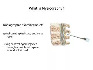
Myelography A myelogram(mi′-e-lo-gram) is a radiographic study of the spinal cord and its nerve root branches with the use of a contrast medium. The spinal cord and nerve roots are outlined by injection of a contrast medium into the subarachnoid space of the spinal canal. The shape and contour of the contrast medium are assessed to detect possible pathologic processes. Because most conditions demonstrated by this procedure occur in the lumbar and cervical areas, myelography of these areas of the spine is most common. Pathologic Indications Myelography is performed when patient symptoms indicate the presence of a lesion that may be present within the spinal canal or may protrude into the canal. If the pathologic process impinges on the spinal cord, patient symptoms may include pain and numbness, often in the upper or lower limbs. The lesions most commonly demonstrated by myelography include herniated nucleus pulposus (HNP), which is the most common clinical indication for myelography, cancerous or benign tumors, cysts, and (in the case of trauma) possible bone fragments. If a lesion is present, myelography serves to identify the extent, size, and level of the pathologic process. Another important feature of myelography is the identification of multiple lesions.
Contraindications Myelography is contraindicated as follows: •Blood in the cerebrospinal fluid (CSF): The presence of blood in the CSF indicates probable irritation within the spinal canal, which can be aggravated by the contrast medium. •Arachnoiditis (inflammation of the arachnoid membrane): Myelography is contraindicated in the case of arachnoiditis because the contrast medium may increase the severity of the inflammation. •Increased intracranial pressure: In cases of elevated intracranial pressure, tapping of the subarachnoid space with needle insertion may cause severe complications to the patient as the pressure equalizes between the areas of brain and spinal cord. •Recent lumbar puncture (within 2 weeks of the current procedure): Performing myelography on a patient who has had a recent lumbar puncture may result in extravasation of the contrast medium outside the subarachnoid space through the hole left by the previous puncture.
Patient Preparation Patients scheduled for myelography may be apprehensive about the procedure. To reduce anxiety and relax the patient, an injectable sedative/muscle relaxant usually is administered 1 hour before the examination. The type and amount of pre-medication used are determined by the radiologist who performs the procedure
Major Equipment The major equipment for myelography includes a radiographic/fluoroscopic room with a 90°/45° (or 90°/90°) tilting table, shoulder braces, and a foot rest with myelography ankle restraints. Shoulder braces and ankle restraints are used to secure the patient during the procedure, which may require tilting of the table in the Trendelenburg position (head lower than feet). Use of shoulder rests and ankle restraints together rather than separately is advised. The foot rest is used to support the patient when the table is moved to the upright position.
Accessory and Optional Equipment Accessory equipment for myelography includes grid cassettes with holders for horizontal-beam radiography, a myelography tray, sterile gloves, an antiseptic solution, appropriate laboratory requisitions, and a large position sponge or pillow. The number and sizes of grid cassettes used depend on the level of the spinal canal that is being examined. The myelography tray is generally a commercial prepackaged, sterilized, disposable unit. A typical tray should contain the following: a razor, a basin and prep sponges, sterile drapes, sterile gauze, 5 ml and 20 ml syringes, 25 gauge and 22 gauge needles, an 18 gauge spinal needle, a single-dose vial of local anesthetic, and three test tubes.
Needle Placement and Injection Process Introduction of contrast medium for myelography is accomplished via puncture of the subarachnoid space. Generally, two locations are used as puncture sites: the lumbar (L3-L4) and cervical (C1-C2) areas. Of these two locations, the lumbar area is safer and easier on the patient and is used most often for the procedure. Cervical puncture is indicated if the lumbar area is contraindicated, or if a pathologic condition indicates complete blockage of the vertebral canal above the lumbar area, obstructing the flow of contrast medium to the upper spinal region. After the puncture site has been selected, the radiologist may use fluoroscopy to facilitate needle placement.
Generally, two body positions are used for a lumbar puncture. The patient may be prone, with a firm pillow or large positioning block placed under the abdomen to flex the spine or may lie in a left lateral position with the spine flexed. Flexion of the spine widens the interspinous space, which facilitates introduction of the spinal needle.
Contrast Media The best type of contrast medium for myelography is one that is miscible (mixes well) with CSF, is easily absorbed, nontoxic, and inert (nonreactive), and has good radiopacity. No one type of contrast medium meets all these criteria. In the past, air or gas (radiolucent) and oil-based iodinated (radiopaque) media have been used for myelography. Currently, however, nonionic, water-soluble iodine-based media are primarily used because of the relatively low osmolality. Water-soluble contrast media provides excellent radiographic visualization of the nerve roots, is easily absorbed into the vascular system, and is excreted by the kidneys. Absorption begins approximately 30 minutes after injection, with good radiopacity evident up to about 1 hour after injection. After 4 to 5 hours, the contrast medium has a hazy radiographic effect, and it is radiographically undetectable after 24 hours.
Dosages: The dosage for myelographic contrast media is recommended by the manufacturer and varies with the concentration of the medium used and the area of the spine under examination. In general, a range of approximately 9 to 15 ml is used. Care should be taken to prevent contrast medium from entering the area of the head. For example, during examination of the cervical area with the patient prone or in Trendelenburg position, the chin is hyperextended to prevent the medium from flowing into the cranial region of the subarachnoid space.
FLUOROSCOPY/SPOT FILMING OR DIGITAL FLUOROSCOPY/IMAGING During fluoroscopy, the table (and patient) is tilted from erect through Trendelenburg positions. This movement facilitates the flow of contrast medium to the area under examination. Under fluoroscopic control, once the contrast medium has reached the desired area, the radiologist may image the patient in a variety of positions from prone to supine and in anterior or posterior oblique positions. Images may be obtained with the use of conventional or digital technology, depending on available equipment. After fluoroscopy, the technologist takes conventional radiographs that are appropriate for the area under examination, as requested by the radiologist.
CERVICAL REGION Horizontal-Beam Lateral The patient is prone, with the arms extended along the sides of the body and the shoulders depressed. The chin is extended and is resting on a small positioning sponge or folded linen for comfort and to maintain extension. The central ray is directed to the level of C4-C5. The field should be collimated to reduce scatter radiation. Respiration is suspended during the exposure.
Cervical region (C7 to T1 region)—swimmer's (horizontal-beam) lateral. The patient is prone, with the chin extended. For a right lateral, the right arm is extended along the right side of the body, with that shoulder depressed. The left arm is flexed (i.e., stretched superior to the head). The central ray is directed to the level of C7. The field is collimated to reduce scatter radiation. Respiration is suspended during the exposure
THORACIC REGION Right Lateral Decubitus Position—AP or PA Projection With Horizontal Beam The patient is positioned in a true right lateral, with the right arm flexed, superior to the head. The left arm is extended and is resting along the left side of the body. To maintain the alignment of the spine parallel to the tabletop, the patient may rest the head on the arm. If needed, a small positioning sponge or folded linen may be placed between the head and the arm to maintain alignment. The central ray is directed to the level of T7. Collimation of the field is applied to the area of interest to reduce scatter radiation. Respiration is suspended during the exposure.
Right or Left Lateral—Vertical Beam The patient is positioned in a true lateral, with the knees flexed. Both arms are semiflexed. The alignment of the spine should be maintained parallel to the tabletop. The patient may rest the head on the hands, or a small positioning sponge or folded linen may be placed between the hands and the head to maintain alignment of the spine. The central ray is directed to the level of T7. The field is collimated to reduce scatter radiation. Respiration is suspended during the exposure
Note: A supine AP and a horizontal-beam lateral generally are not recommended because in the supine position, pooling of contrast medium occurs in the midthoracic region as a result of the usual thoracic curvature. This pooling, of course, is more prominent in some patients. Therefore, to best demonstrate the entire spinal canal of the thoracic region, AP and PA projections should be taken in both right and left lateral decubitus positions, in addition to the vertical-beam lateral position as described and illustrated.
LUMBAR REGION Semierect Lateral—Horizontal Beam The patient is positioned prone, with the arms flexed superior to the head. The table and the patient are semierect. The radiologist, under fluoroscopic control, adjusts the angulation of the table to concentrate the contrast medium in the lumbar area. The central ray is directed to L3. Collimation to the area of interest is important to reduce scatter radiation. Respiration is suspended during the exposure. Additional positions may include obliques with a vertical or horizontal beam and a supine AP projection.
RADIOGRAPHIC CRITERIA (FOR ALL LEVELS OF THE SPINAL COLUMN) •The appropriate level of the spinal column, with contrast present, should be demonstrated. •Correct exposure and adequate penetration help to demonstrate anatomy and contrast medium. •Patient ID markers and anatomic markers (right or left) should be clearly visualized without superimposing anatomy. •Collimation should be evident.