Download
1 / 22
220 likes | 360 Vues
Status and Plan of GDE Design Work (Including Road Map for RDR). Feb. 17 2006 PAL Eun-San Kim. ILC Meetings. Snowmass, Colorado, 14-17 Aug. 2005 : Started BCD European GDE meeting, Oxford, 25 Oct. 2005 Damping ring workshop, CERN, 9-11 Nov. 2005

E N D
Status and Plan of GDE Design Work (Including Road Map for RDR) Feb. 17 2006 PAL Eun-San Kim
ILC Meetings • Snowmass, Colorado, 14-17 Aug. 2005 : Started BCD • European GDE meeting, Oxford, 25 Oct. 2005 • Damping ring workshop, CERN, 9-11 Nov. 2005 • GDE meeting, Frascati, Italy 7-9 Dec. 2005 : Decided BCD • 1st Area System meeting, KEK, 19-20 Jan. 2006 : Discussed machine layout and boundary between area systems • Lattice design meeting, CERN, 6-8 Feb. 2006 • 2nd Area System meeting, FNAL, 13-14 Feb. 2006 • GDE meeting, Bangalore, 9-11 March 2006 • 3rd Area system meeting, DESY, April 2006 • GDE meeting, Vancouver, 19-23 July 2006 • GDE meeting, Valencia, Autumn 2006
Frascati GDE Meeting Discussed progress since Snowmass Finally agreed BCD to be documented. - includes baseline and alternative designs Organized the GDE group for RDR in 2006 Final BCD becomes property of CCB in early 2006
Frascati GDE MeetingBCD layout IP • Working Group for BCD WG1 : LET beam dynamics WG2 : Main Linac WG3a : Sources WG3b : Damping Rings WG4 : Beam Delivery WG5 : SCRF Cavity
Frascati GDE Meeting Matrix group for RDR C. Adolphsen H. Hayano L. Lilje N. Solyak J. Gao S. Guiducci A. Wolski D. A-K A. Seryi H. Yamamoto M. Kuriki J. Sheppard E.-S. Kim P. Tenenbaum A. Brachmann Area system is geographical breakdown of machine for design and cost estimation
1st Area system meetingBaseline Layout (500 GeV) - 1st stage : 500 GeV - 2nd stage : 1 TeV ; Moving of turn-around and BC No moving of DR
Electron source in BCD 120 keV DC Gun 70-100 MeV 12 MeV laser 400 MeV SC Linac Eacc = 17.8 MV/m NC pre-accelerator diagnostic section NC SHB+solenoid
Positron source in BCD To IP Undulator ~100m e- Accelerating structure e+ To DR 150 GeV e- Ti Alloy Target
Damping Ring in BCD • Baseline e+ : two 6 km rings e- : one 6 km ring • Alternative e+ : 6 km, 17 km Baseline
DR Tasks List for RDR • Lattice design - 6 km e-/e+ rings : L. Emery, A. Xiao, E-S Kim, Y. Sun - 17 km e-/e+ rings : Y. Cai, Y. Yan - Injection and extraction lines : A. Wolski • Acceptance: Y. Cai, Y. Yan, A.Wolski • Low-emittance tuning: J. Jones • Impedance : M. Venturini, K. Bane, S. Heifets, etc • Electron-cloud : M. Pivi, C. Celata, K. Ohmi etc.
DR Tasks List for RDR • Ion-effects : L. Wang, E-S Kim, K. Ohmi, M. Venturini, G. Xia • Other collective effects : S. Mtingwa, M. Venturini, S. Santis, A. Wolski • Injection/extraction kickers : pulser : J. Urakawa, T. Naito, M. Ross, A. Krasnykh, etc • Injection/extraction kickers : striplines : A. Krasnykh, S. Santis, D. Alesini, F. Marcellini
Baseline Damping Ring Circumference 6.6 km Energy 5 GeV RF frequency 650 MHz Harmonic number 14402 Damping time < 25 ms (e+) < 50 ms (e-) Emittance 5 mm Bunch length 6 mm Energy spread < 0.13 % Momentum compaction 4x10⁻⁴ Damping wiggler peak field 1.6 T Damping wiggler period 0.4 m Energy acceptance < 0.5 % Dynamic aperture Ax+Ay < 0.09 m-rad
Baseline Damping Ring Bunch filling patterns for e-
Fast-ion effects in Baseline Damping Ring 650 MHz, 5400 bunch Beam size per 50 turns Sqrt(Jy)
Lattice Design of Electron damping ring One straight section One Arc and Wiggler section A lattice with low average beta-functionsto reduce the effects of fast-ion. Tele-conference for e- DR lattice will be at the beginning of March.
Ring to Main Linac (RTML) Status and Plans • Started works for shorter bunch compressor and turn-around optics • Contacted leaders of all technical and global systems • Milestone - Review RTML design and place lattices and documentation under change control in April 2006
Ring to Main Linac (RTML) RTML Layout Turn around eny = 0.02 mm, 3.2 nC, sz = 6mm Total 2.5 km sz= 0.15 mm SR BC 1 BC 2
Ring to Main Linac (RTML) Bunch compressor
Ring to Main Linac (RTML) Bunch compressor • Each BC in baseline has 240 meters of bend magnets arranged in chicanes : Long ! • Considering two approaches to reduce length • Enhancing R56 by forcing nonzero dispersion at Qs • Replacing wiggler with 4-bend chicane with optimized lattice functions for emittance preservation
Main Linac in BCD • Baseline in 1st stage - TESLA cavity type - Operation gradient = 31.5 MV/m, Qo=1010 • Baseline in 2nd stage - LL or RE cavity type - Operation gradient = 36 MV/m, Qo=1010 - Total length = 41 km • Alternative in 1st stage - LL or RE cavity type - Operation gradient = 36 MV/m • Linac RF basic unit -1 modulator, 1 klystron, 3 cryomodules, 27 cavities
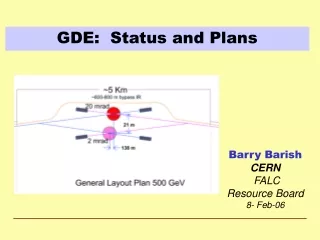
Beam Delivery System in BCD • Baseline : • - 2 IPs for 2 mrad and 20 mard • - 150 m longitudinal separation between 2 IPs • Alternative : • - 1 IP
Summary • Bangalore GDE meeting - starting for estimation of costs • RDR will be finished in Dec. 2006 - RDR is not complete technical design, but is a design to estimate reliable cost. • TDR will be completed in Dec. 2008.