Download
1 / 22
220 likes | 251 Vues
This article discusses the evolution of the GDE BDS design based on talks presented by area leaders at the Vancouver meeting. It delves into the evaluations, cost estimates, and the shift from 20/2 to 14/14 configurations. Detailed analysis and conclusions from the MDI panel are also summarized.

E N D
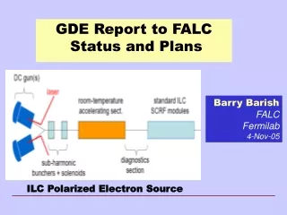
Status of GDE BDS Design Talk based on several talks presented by BDS area leaders Andrei Seryi, Hitoshi Yamamoto, Deepa Angal-Kalinin at and after Vancouver Deepa Angal-Kalinin LC-ABD Plenary Meeting Durham, 25th September 2006
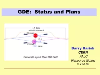
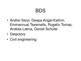
Vancouver baseline • Two IRs with 20mrad and 2mrad crossing angle • Two collider halls separated longitudinally by 138m b-collim. 2mr IR Diagnostics BSY tune-up dump E-collim. FF 20mr IR grid is 100m*5m Global Design Effort
Evaluation of baseline before Vancouver • Evaluation of the differences between 20mrad and 2mrad IRs and extraction lines focused on • study of physics reach • background conditions in IR • radiation conditions in extraction lines • performance of downstream diagnostics • technical feasibility of magnets • power consumption and cost Global Design Effort
Cost of different configuration • The WBS includes counts, lengths, or cost fractions from different subsystems of BDS: • WBS has ~240 input lines * 39columns not including the sub-WBSs • This allows calculating the total cost and also the common cost, additional cost for 20mrad IR and additional cost for 2mrad IR Example Global Design Effort
Overall cost: BDS 20/2 baseline • Cost drivers • CF&S • Magnet system • Vacuum system • Installation • Dumps & Collimators • Control • Instrumentation Global Design Effort
Vancouver BDS Cost Estimates Additional costs for IR20 and IR2 Global Design Effort
Cost of different configurations Global Design Effort
2 mrad and 20 mrad IRs • Small separation of extraction and incoming beams in 2 mrad case • Complicated magnets • Backscattered radiation in IR • Long extraction line with larger apertures • Higher cost and technically more difficult • 20 mrad based on compact SC quadrupoles developed at Brookhaven • Technology works down to ~14 mrad crossing • Physics impact of 14 mrad vs 2 mrad is small • Design well studied and developed Global Design Effort
CF&S conceptual layout Two IRs 20 mrad and 2 mrad Two IRs 14 mrad/ 14 mrad Global Design Effort
At Vancouver • Discussion of 20/2 baseline situation • by BDS area leaders • with present colleagues from BDS group • with MDI panel • with WWS organizing committee • with EC and GDE director • It was decided to cut the Gordian knot of the cost, technical and non-technical issues and propose to change the baseline to two IR with 14/14 configuration • Design & cost of 14/14 with common collider hall & z=0 • Design of 14mr beamline is almost the same as for 20mrad • In the 14/14 cost estimation, the following adjustments were estimated and taken into account: removed stretches in optics; shorter (~11mr/14mr) tapered tunnels; remove one surface building; savings due to common hall (but volume still twice the single volume); add cost of 42% more gradient bends (for 14mrad bend), their PS, BPMs, movers, etc Global Design Effort
After Vancouver : Submission of CCR, evaluation by WWS, MDI & CCB • CCR for 14/14 configuration submitted on July 28 • MDI panel meeting on Aug. 15 to discuss • 14/14 configuration • single collider hall • 5m muon spoilers instead of 9m+18m • on-surface detector assembly • The MDI panel accepted those changes. The conclusions were sent to WWS and CCB. • The WWS OC was asked to comment about the first two items and also accepted them • CCB considered the CCR for 14/14, and on September 8 issued a recommendation for EC to adopt the CCR. <= CCR submitted on July 28 <=CCR submitted on Sept. 8 <= CCR submitted on September 21 Global Design Effort
From minutes of MDI panel (shortened quote) • The (physics) mode most affected by crossing angle is the slepton pair production where the slepton-LSP Dm is small. The main background is 2-g processes and an efficient low-angle electron tag by BEAMCAL is needed to veto them. • For a large crossing angle (14 or 20mrad), anti-DID is needed to collimate the pair background along the outgoing beam. For 14mrad crossing with anti-DID, the … background is expected to be comparable to the 2mrad case while the signal efficiency reduces by about 30% to 40%. This is mainly due to the 2nd hole of BEAMCAL that is needed for the large crossing angle which will force additional cuts to remove the 2-photon and other backgrounds. • This is not based on a complete analysis but on a study of the pair background distribution on the BEAMCAL: that for 20mrad crossing with anti-DID was found to be essentially the same as the 2mrad case. A complete analysis is needed for 14mrad with anti-DID, also covering different values of the mass difference (namely, for different SUSY parameter space). Backgrounds considered here are mainly the pair background and a lesser extent Bhabha events. More studies are sorely needed in this area. • With this limited information, the MDI panel thinks that the 14mrad is acceptable as the baseline at this time. However, we would like to stress that the 2mrad crossing angle is clearly desirable than larger crossing angles for the slepton search, and R&Ds related to 2mrad should be encouraged. * LSP= lightest super-symmetric particle Global Design Effort
Muon walls • Purpose: • Personnel Protection: Limit dose rates in one IR when beam sent to other IR or to the tune-up beam dump • Physics: Reduce the muon background in the detectors Scheme of a muon wall installed in a tunnel widening which provide passage around the wall Baseline configuration: 18m and 9m walls in each beamline Global Design Effort
Muon walls CCR • Baseline (18m+9m walls) reduce muon flux to < 10muons/200bunches if 0.1% of the beam is collimated • Considered that • The estimation of 0.1% beam halo population is conservative • The min muon wall required for personnel protection is 5m • Detector can tolerate higher muon flux* • Cost of long muon spoilers is substantial • Suggested CCR to install initially only 5m single walls • The caverns will be built for full length walls, allowing upgrade • Such upgrade could be done in ~3month * With single 5m wall there is ~400muon/200bunches (500 GeV CM, 0.1% of the beam collimated) which corresponds to ~0.15% occupancy of TPC Global Design Effort
On-surface (a la CMS) assembly • According to tentative CF&S schedule, the detector hall is ready for detector assembly after 4y11m after project start • If so, cannot fit into the goal of “7years until first beam” and “8years until physics run” • Surface assembly allows to save 2-2.5 years and allows to fit into this goal • The collider hall size is also smaller in this case • A building on surface is needed, but savings are still substantial • A CCR to on-surface assembly will save some money depending on what we agree upon with respect to collider hall size, shafts, handling equipment etc. Global Design Effort
CMS detector assembly approach: • Assembled on the surface in parallel with underground work • Allows pre-commissioning before lowering • Lowering using dedicated heavy lifting equipment • Allows saving up to 3years of time • Reduce size of underground hall required • Accepted by MDI panel for ILC Global Design Effort
Tentative layout of 14/14 configuration • Common IR hall ~100m (L) x 30m (W) at z=0 with 28.4m DX • 4m tunnels in all BDS • Alcoves 4*6m every 100m, no service tunnel • Small 0.8m shaft for lasers near laser wire, upstream and downstream diagnostics • Long muon walls (9m & 18m) replaced by single 5m wall • Passages near muon walls (main and spare one) • 9m machine access shaft in the “BDS triangle” • Shortened extraction line • Shorter tapered tunnels Global Design Effort
Further work baseline cost • Optimizing the IR hall requirement and detector assembly procedure • Optimizing CF&S design • Working on installation model and refining the cost • Reviewing systems for possible cost reductions • Discussing other possible cost saving strategies Global Design Effort
Director’s corner : ILC Newsletter 21st Sep The evolving ILC Design : Changing the crossing angles “Interestingly, the original motivation for the 2mrad x 20mrad configuration was partially based on the perceived complementary physics capabilities of having different crossing angles, as well as different technical risks. …………….. This is the first change request since reliable cost information has been available. Therefore, it marks the first time we have been able to make decisions based on weighing all the factors: cost, risk and science performance. In order to assess the scientific impacts of the change, the Change Control Board formally asked the World Wide Study for input. In turn, the WWS solicited inputs from the physics community and submitted a written report. They supported the change but under the provision that R&D for small-angle crossing continues, allowing for a reconsideration of the small angle option at a later date. “ Global Design Effort
Director’s corner : ILC Newsletter 21st Sep The evolving ILC Design : Changing the crossing angles “Although this action is now completed, it may well not be the end of the story. This change prompts consideration of further optimisation of the design for 14 mrad crossings, including a reconsideration of the muon shielding problem, how to preserve the upgrade option to 1 TeV with minimal up-front investment, and finally whether employing a single beam line and interaction region is a viable option to consider. Using the same interaction point to serve two complementary detectors, this push-pull system (meaning the two detectors alternately move on and off the beamline) would eliminate an entire expensive beam line. We plan to form a special group of experimentalists, accelerator physicists and engineers to do a careful study before Valencia, where we will schedule an informed discussion of this option with the ILC community.” Global Design Effort
B. Barish – MAC Meeting, KEK, 20-22 Sep • Reference Design Report • A complete documented technical concept • Three reports : RDR – Reference Design Report : DCR – Detector Concept Report; Companion Volume for Policy Makers and other non experts • Process of Establishing Reference Design • Parametric Optimization of Cost vs Physics Potential • WWS consulted on all changes, as well as MDI group • ILCSC Parameters Group (R Heuer) reformed and they are working with us to optimize parameters for cost / performance. • Schedule • Most changes before Valencia; some like 1 IR push pull studied but decision deferred for discussions at Valencia. • Draft RDR released couple months later – (Beijing February ?) Global Design Effort
Thank you for your attention! Global Design Effort