Download
1 / 21
210 likes | 364 Vues
This presentation, led by Danielle Smith, Shawn Purnell, and Chris Hawk, explores an innovative proof-of-concept project that simulates low-resolution physiological control of a computer cursor. Designed for paraplegic empowerment, the system utilizes electroencephalography and electromyography via electrodes to translate physiological signals into actionable cursor movements. The presentation outlines the system's hardware and software implementations, discusses its outcomes, and envisions future developments aimed at enhancing functionality for practical applications in both medical and military settings.

E N D
Physiological Control of a Computer Mouse Presented by Danielle Smith, Shawn Purnell, & Chris Hawk
Outline of Presentation • Project Introduction • Background/Theory • Block Diagram • Hardware Circuit Implementation • Software Implementation • Results/Discussion • Future Developments • Conclusion
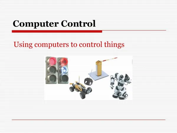
Introduction • Project Purpose • Acts as a proof of concept project • Simulate low resolution physiological directional control of an automated computer cursor • for paraplegic empowerment • for military strategic targeting systems
Background on Electrodes • Silver/Silver-Chloride Electrodes • Contact/ Capacitive electrodes • Serve as a transducers to change an ionic current into an electronic current • Ag/AgCl Electrodes used for measurements • Electrodes used for EOG • Small with solid gel • Prevent motion artifact and contact with eye • Electrodes used for EMG • Large with liquid gel
EMG and EOG Signals • EMG measurements - lie within muscle movement • Skeletal muscle organized on basis of motor unit • Motor unit - smallest unit that can be activated by volitional effort • Fibers of a given motor unit are interspersed with fibers of other motor units • At high levels of effort and contraction, many motor unit responses are superimposed • Gives Rise to the complicated interference pattern taken as the signal • EOG signal - based on dipole within the eye • There is a steady corneal-retinal potential from the back of the eye to the front of the eye • This steady dipole may be used to measure eye potential by placing surface electrodes around the eyes
Biopotential Differential Amplifier • Three stage gain • High input impedance • Variable resistor to minimize common mode gain • Low gain in dc-coupled stages to minimize offset potentials produced by electrodes • Bandpass filter in third stage
EOG Circuit Design • EOG parameters • frequency range: 0 - 10 Hz • voltage amplitude: 50 - 3500 µVolt • EOG Amplifier theoretical values • Frequency response: .048 - 5.3 Hz • Gain of approximately 21 for dc-coupled stages • Overall gain: 14,000
EOG Hardware Schematic • High Cutoff Frequency: 4.5 Hz • Low Cutoff Frequency: 0.05 Hz • Midband Frequency Range: 0.25 - 1.5 Hz • Midband Gain: 16,090
EMG Circuit Design • EMG parameters • frequency range: dc - 10,000 Hz • voltage amplitude: 0.1 - 5 mVolt • EMG Amplifier theoretical values • Frequency response: 241 Hz - 5.3 kHz • Gain of approximately 21 for dc-coupled stages • EMG signal processed by diode and LPF • Overall gain: 15,000
EMG Hardware Schematic • High Cutoff Frequency: 4.7 kHz • Low Cutoff Frequency: 250 Hz • Midband Frequency Range: 2.1 - 2.5 kHz • Midband Gain: 15,828
Specification Testing • Common Mode Tests • Common mode output voltages less than 10% the signal • Minimize common mode gain • dc-Coupled Stage Gain Tests • dc-coupled stage gain of less than 25 • to prevent saturation of amplifiers
Results and Discussion • Frequency Response Tests • Frequency responses were as predicted theoretically • Common Mode Tests • Common mode output voltage fall within 10% of their signals • dc-Coupled Stage Gain Tests • dc-coupled stage gain for all three amplifiers were approximately 25
Goals of Software • Goals of Software • Acquire continuous analog signals • Create logic to process signals • click for EMG jaw clench • grid for EOG eye movement
Data Acquisition • Scales analog signals into a one-dimensional array • Indexes the data by channel • Separates individual data within specified channel
Design Complications and Alterations • Complications • Improper installation of LabVIEW • Alterations • EOG amplifier high cutoff frequency reduced from 10 Hz to 4 Hz to minimize high frequency components in the signal • Summer circuits were found to be unnecessary • Comparator implemented into LabVIEW
Future Development • Project acts as proof of concept • Software Development • Create more resolution in software implementation by creating a counter-based system • Apply to actual computer mouse connector • Hardware Development • Replace electrodes with high sensitivity magnetic sensors • Replace bioamplifiers with amplifiers designed for the magnetic sensor outputs • Develop marketable product
Conclusion • Successful Overall Results in obtaining project goals • Project proves that directional control and clicking simulation can be achieved through facial physiological manipulation • Questions ???