Download
1 / 30
300 likes | 408 Vues
Haptic Simulation of Linear Elastic Media with Fluid Pockets. A.H. Gosline ( andrewg [at] cim.mcgill.ca) S.E. Salcudean (tims [at] ece.ubc.ca) J. Yan (josephy [at] ece.ubc.ca). Introduction. Haptic simulation becoming increasingly popular for medical training. Issues addressed:

E N D
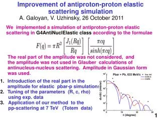
Haptic Simulation of Linear Elastic Media with Fluid Pockets A.H. Gosline (andrewg [at] cim.mcgill.ca)S.E. Salcudean (tims [at] ece.ubc.ca)J. Yan (josephy [at] ece.ubc.ca)
Introduction Haptic simulation becoming increasingly popular for medical training. Issues addressed: • Tissue models assume continuous elastic material. • Fluid structures ignored. • Haptics requires update rates of order 500 Hz. Photos appear courtesy of Iman Brouwer and Simon DiMaio Robotics and Control Laboratory
Spring-Mass-Damper Cotin et al. (2000) D’Aulignac et al. (2000) -Pros: Simple to implement. Easy to change mesh. -Cons: Sensitive to mesh topology Coarse approximation to continuous material. BEM, FEM James & Pai. (2001) DiMaio & Salcudean. (2002) -Pros: Accurate description of elastic material. -Cons: Large computational cost. Difficult to change mesh. Requires pre-computation. Fast Deformable Methods Robotics and Control Laboratory
Fluid Modeling with FEM Navier-Stokes Fluid. Basdogan et al. (2001), Agus et al. (2002). • Dynamic analysis, large computational effort. • In surgery simulators for graphics only (10-15Hz). Irrotational Elastic Elements. Dogangun et al. (1993, 1996). • Statics and Dynamics (not flow). • Decoupling of fluid-elastic. • Poor scaling. Hydrostatic Fluid Pressure. De and Srinivasan (1999). • Quasi-static. • Arbitrary pressure/volume relationship. • Force boundary condition. Robotics and Control Laboratory
Hydrostatic Fluid Pressure • Force boundary condition applied normal to fluid-elastic interface. • Static force balance to distribute force over each element. • Pressure-Volume relationship. Robotics and Control Laboratory
Pressure-Volume Relationship Negative Pressure Positive Pressure Robotics and Control Laboratory
Pressure-Volume Relationship • Approximate nonlinear P-V relationship with line fit. • Slope ~24kPa • Use as optimal gain for control law. Robotics and Control Laboratory
Numerical Method • Proportional feedback update: Pi+1 = Pi + Kp Errori • Errori = Vo - Vi • Pressure to Volume transfer function: • Distribute pressure over boundary • Solve FEM • Compute volume • Iterate until Error < Tolerance. Errori Vo Kp - KpErrori FEM Vi Disturbance from tool Robotics and Control Laboratory
Performance • With P-V slope as gain, the performance is good. • Convergence to 1% tolerance in maximum 1 iteration for small strains. • Robust to large deformations of up to 30% Compressible Fluid Incompressible Fluid Robotics and Control Laboratory
Phantom Construction • 13% type B Gelatin. • 3% Cellulose for speckle. • Glove finger tip filled with fluid. Robotics and Control Laboratory
Experimental Apparatus Force Sensor • Ultrasound probe to capture fluid pocket shape (left). • Top surface of phantom marked for surface tracking (center). • Force sensor (right). • 3DOF Motion Stage for compression (far right). • All components rigidly mounted to aluminum base plate. Motion Stage US Probe Phantom Robotics and Control Laboratory
Mesh Generation Robotics and Control Laboratory
US Contour Results No Displacement Robotics and Control Laboratory
US Contour Results 3mm Displacement Robotics and Control Laboratory
US Contour Results 6mm Displacement Robotics and Control Laboratory
US Contour Results Largest deviation ~ 11% 9mm Displacement Robotics and Control Laboratory
Surface Tracked Results Robotics and Control Laboratory
Real-time Haptic Simulation • Incompressible fluid added to the needle insertion simulator by DiMaio and Salcudean (2002). • Software runs at fixed update rate of 512 Hz. • Haptic loop fixed at 2 iterations per update. Robotics and Control Laboratory
Simulation: Volume Response Robotics and Control Laboratory
Simulation: Pressure Response Robotics and Control Laboratory
Conclusions • Linear FEM with hydrostatic pressure predicts the deformation of an incompressible fluid-filled phantom in a realistic manner up to approximately 15% strain. • Fast numerical method optimized with understanding of P-V relation gives fast convergence. • Matrix condensation allows for real-time haptic rendering of a fluid-filled deformable object at 512Hz. Robotics and Control Laboratory
Future Work • Interactive haptic simulation of fluid-filled structures in 3D • Investigate validity of pressure computation • Validate for vascular anatomy • Psychophysics experiments Robotics and Control Laboratory
Questions ?? • Acknowledgements • Rob Rohling for OptoTrak and Ultrasound. • Simon DiMaio and RCL Labmates • Simon Bachman and Technicians Robotics and Control Laboratory
Pressure, Volume and Flow • Bernoulli’s Equation: For incompressible, steady nonviscous flow, P + ½ V2 + gh = constant along streamline • Navier-Stokes Equations: Robotics and Control Laboratory
Approach • Linear FEM with condensation • Accurate elastic model. • Condensation. • Interior nodes. • Hydrostatic Fluid Pressure • Incompressible fluid enclosures. • Flow relationships. • Force boundary condition. Robotics and Control Laboratory
Gelatin Properties • Linear elastic to ~ 15% strain. • E ~ 15.2 kPa Robotics and Control Laboratory
Linear Elastic Finite Elements Hooke’s Law, σ =D ε E(u)strain = ½∫Ω εTσ dx, ε = Bu = ½∫Ω(Bu)T DBu dx δE(u)strain = 0 = ∫ΩBeTD Beu dx – f K u = f Robotics and Control Laboratory
Errori Pi+1 Vo Kp - Z-1 FEM Vi Pi Disturbance from tool Numerical Method • Proportional feedback control method. • Pressure update law: Pi+1 = Pi + K Errori • FEM transfer function computes V with P as input. • Iterate until Error < Tol. • “Tune” the controller for optimal performance Robotics and Control Laboratory
Conclusions • Linear FEM predicts 3D deformation of an incompressible fluid-filled cavity in realistic manner. • Optimized gain allows fast convergence. • Linear FEM and matrix condensation allow for haptic display. Future Work • Interactive Haptic Simulation in 3D. • Investigate validity of pressure prediction. • Validation for modeling of vascular anatomy. • Psychophysics experiments. Robotics and Control Laboratory
Acknowledgements • Rob Rohling for OptoTrak and Ultrasound. • Simon DiMaio and RCL Labmates • Simon Bachman and Technicians Robotics and Control Laboratory