Operating In Protected Mode
Microprocessor Architecture. UOP S.E.Comp (Sem-I). Operating In Protected Mode. Prof.P.C.Patil Department of Computer Engg Matoshri College of Engg.Nasik pcpatil18@gmail.com. lntroduction. lntroduction.

Operating In Protected Mode
E N D
Presentation Transcript
Microprocessor Architecture UOP S.E.Comp (Sem-I) • Operating In Protected Mode Prof.P.C.Patil Department of Computer Engg Matoshri College of Engg.Nasik pcpatil18@gmail.com.
lntroduction • The complete capabilities of the 80386DX are unlocked when the 803B6DX operates in protected mode. • After reset 80386DX enters into real mode but setting bit 0 in CRO register it is possible to operate 80386DX in protected mode.
Features of protected mode • Protected mode vastly increases the linear address space to 4 Gigabytes (232 bytes) and allows the running of virtual memory programs of almost unlimited size (64 terabytes or 246 bytes ). • Protected mode allows the 80386DX to run all of the existing 8086 and 80286 programs. • It provides a sophisticated memory management and a hardware-assisted protection mechanism. • It provides special 80386 instructions for multitasking operating systems. • It supports paging mechanism.
Protected Mode Register Model • Global Descriptor Table Register (GDTR) - 48 bits : • It holds the 32-bit linear base address and 16-bit limit of the Global Descriptor Table (GDT). • lnterrupt Descriptor Table Register (IDTR) - 48 bits : • It holds the 32-bit linear base address and 16-bit limit of the Irterrupt Descriptor Table (IDT). • Local Descriptor Table Register (LDTR) - 16 bits : • It holds the 16-bit selector for the local descriptor table • Task Register (TR) 16 bits : • It holds the 16 bit selector for the task state segment descriptor. Link
Protected Mode Register Model In protected mode register set, funcfion of few registers have been extended. • The instruction pointer is now 32bit.Called as EIP. • More bits of the flag registers (EFLAGs) are active • All four control registers CR0-CR3 are active
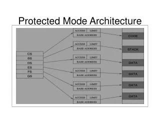
Protected Mode Addressing Mechanism • The 80386 DX has three distinct address spaces : • Logical, • Linear and • Physical • A logical address (also known as virtual address) consists of a selector and an offset. • A selector is the contents of a segment register
Protected Mode Addressing Mechanism • In real mode : the segmentation unit shift’s the selector left four bits & adds the result to the offset to form the linear address. • In protected mode : Every segment selector has a linear base address associated with it, and it is stored in the segment descriptor. • A selector : is used to point a descriptor for the segment in a table of descriptors. • The linear base address from the descriptor is then added to the 32 Bit offset to generate the 32-bit linear address. • This process is known as segmentation
Protected Mode Addressing Mechanism • If paging unit is not enabled then the 32-bit linear address corresponds to the physical address. • But if paging unit is enabled, paging mechanism translates the linear address space into the physical address space by paging translation.
Segment Descriptor • In protected mode, Memory Management Unit (MMU) uses the segment selector to access a descriptor for the desired segment in a table of descriptors in memory. • Segment descriptor is a special structure which describes the segment. • Exactly one segment descriptor must be defined for each segment of the memory.
Segment Descriptor • Descriptors are eight type quantities which contain attributes about a given region of linear address space (i.e. a segment). • These attributes include • the 32-bit base linear address of the segment, • the 20-bit length and granularity of the segment, • the protection level, • read, write or execute privileges, • the default size of the operands (15-bit or 32Bit), and • the type of segment.
Segment Descriptor • Base : • It contains the 32-bit base address for a segment. • Thus defines the location of the segment within the 4 gigabyte linear address space. • The 80386 concatenates the three fragments of the base address to form a single 32-bit address. • Limit : • It defines the size of the segment. • The 80386 concatenates the two fragments of the limit field to form a 20 bit value. • The 80386 interprets this 20-bit value in two ways, depending on the setting of the granularity bit (G) : • If G bit 0 : In units of 1 byte, to define a limit of up to 1 M byte (220) • If G bit 1. : In units of 4 kilobytes, to define a limit of up to 4 gigabytes.
Segment Descriptor • Granularity Bit : • It specifies the units with which the limit field is interpreted. • When bit is 0, the limit is interpreted in units of one byte; otherwise limit is interpreted in units of 4 Kbytes. • 0 (Reserved by lntel) : • It neither can be defined nor can be used by user. • This bit must be zero for compatibility with future processors. • AVL/U (User Bit) : • This bit is completely undefined, and 80386 ignores it. This is available field/bit for user or operating system.
Segment Descriptor Access rights byte : • P (Present Bit) : • The present P bit is 1 if the segment is loaded in the physical memory, if P = 0 then any attempt to access this segment causes a not present exception (exception 11). • DPL (Descriptor Privilege Level) : • It is a 2-bit field defines the level of privilege associated with the memory space that the descriptor defines – DPL0 is the most privileged whereas DPL3 is the least privilege • Type : • This specifies the specific descriptors among various kinds of descriptors.
Segment Descriptor • S (System Bit) : • The segment S bit in the segment descriptor determines if a given segment is a system segment or a code or a data segment. • If the S bit is 1 then the segment is either a code or data segment, if it is 0 then the segment is system segment. • A (Accessed Bit) : • The 80386 automatically sets this bit when a selector for the descriptor is loaded into a segment register. • This means that 80386 sets accessed bit whenever a memory reference is made by accessing the segment.
Types Segment Descriptor: Non-System Segment Descriptors Non-System Segment Descriptors Data Segment Descriptor
Types Segment Descriptor: Non-System Segment Descriptors Code Segment Descriptor
Types Segment Descriptor: System Segment Descriptors Systeme Segment Descriptor
Types Segment Descriptor: System Segment Descriptors Gate Descriptor
Descriptor Table • Segment descriptors are grouped and placed one after the other in contiguous memory locations. • This group arrangement is known as a descriptor table. • The maximum limit for the length of descriptor table is 64 kbytes and each descriptor takes 8 bytes to store the information of a particular segment. • So descriptor table can have as many as 8192 descriptors. • The upper 13 bits of a selector are used as an index into the descriptor table.
Descriptor Table There are three types of descriptor tables : • Global Descriptor Table (GDT) : • It is a general purpose table of descriptors, can be used by all programs to reference segments of memory. • The GDT can have any type of segment descriptor except for descriptors which are used for serving interrupts. • Interrupt Descriptor Table (IDT) : • It holds the segment descriptors that define interrupt or exception handling routines. • The IDT is a direct replacement for the interrupt vector table used in 8085 system. • Local Descriptor Tables (LDT) : • They are set up in the system for individual task or closely related group of tasks.
Descriptor Table : GDTR • GDTR is a 48-bit register located inside the 80386DX. • The lower two bytes of this register specifies the LIMIT (in bytes) for the GDT. • The value of limit is 1 less than the actual size of the table. • For example, if LIMIT is 03FFH then the table is 1024(1023 +1) bytes in length (03FFH =102316). • Since the LIMIT field is 16 bit long, the GDT can grow up to 65,536 bytes long. • The upper four bytgs of GDTR specifies the 32-bit linear address of the base of the Global Descriptor Table (GDT).
Descriptor Table : IDTR • Like global descriptor table register, Interrupt descriptor table register (IDTR) holds the 16-bit limit and 32-bit linear address of the base of the Interrupt Descriptor Table (IDT). • Interrupt Descriptor Table Register are used to define a Interrupt Descriptor Table (IDT) in the 80386DX physical memory address space. • Like GDTR the IDTR is also 48 bit in length, with lower two bytes defines Limits and upper 4 bytes defines the base address. • Since limit field is two bytes, the IDT can also be up to 65,536 bytes long. • But the 803B6DX only supports upto 256 interrupts or exceptions; • therefore, the size of the IDT should not be set to support more than 256 interrupts.
Descriptor Table : LDTR • Unlike GDTR and IDTR, the LDTR is a 16-bit register. • It does not specify any limit or base address for the segment but it specifies the address of the LDT descriptor stored in the Global Descriptor Table (GDT) • LDTR holds a selector that points to an LDT descriptor in the GDT. • Whenever a selector is loaded into the LDTR, the corresponding descriptor is located in the global descriptor table. • The contents of this descriptor defines the local descriptor table. • The 32-bit base value defines starting point of the table in the 80386DX physical memory address space and 16-bit limit specifies the size of the table.
Descriptor Table : LDTR • The GDT can contain many LDT descriptors. • To put particular LDT in service, it is necessary to load the LDTR with corresponding selector. • For loading the values in GDTR, IDTR and LDTR registers, 80336DX provides LGDT, LLDT, and LIDT instructions. • It also provides SGDT, SLDT and SIDT instructions. • These (48 bits) instructions copy the contents of the descriptor table registers into the six bytes of memory pointed by the destination operand. • These tables are manipulated by the operating system. • Thus, the instructions used for loading the descriptor tables are privileged instructions.
Segmentation • Segmentation is a process of converting logical address into a linear address. • The 13-bit index part of selector is multiplied by 8 and used as a pointer to the desired descriptor in a descriptor table. • The index value is multiplied by 8 because each descriptor requires 8 bytes in the descriptor table. • The descriptor in the descriptor table contains mainly base address, segment limit and access right byte. • The 80386 adds the base address from the descriptor to the effective address or offset to generate a linear address.
Segmentation • The selector component of each logical address contains 2 bits which represent the privilege level of the program section requesting access to a segment. • Level 0 is the most privileged and level 3 is the least privileged. • More previleged levels are numerically smaller than less privileged levels. • The descriptor of each segment contains 2 bits which represent the privilege level of that segment. • When an executing program attempts to access a segment, the memory management unit compares the privilege level in the selector with the privilege level in the descriptor
Segmentation • If the segment selector has the same or greater privilege level, then the memory management unit allows the segment to be accessed. • If the selector privilege level is lower than the privilege level of the segment, the memory management unit denies the access and sends an interrupt signal to the CPU indicating a privilege level violation.