Download
1 / 30
300 likes | 332 Vues
Explore Faraday's experiments and Lenz's law, showing how changing magnetic fields induce current in electrical devices. Learn about the principles of flux and induction in electronic circuits.

E N D
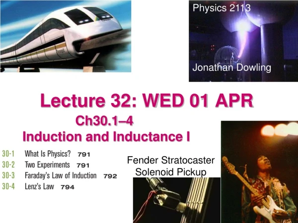
Physics 2113 Jonathan Dowling Lecture 32: WED 01 APR Ch30.1–4 Induction and Inductance I Fender Stratocaster Solenoid Pickup
Magnetic Circuit Breaker As the normal operating or "rated" current flows through the sensing coil, a magnetic field is created around that coil. When the current flow increases, the strength of the magnetic field increases, drawing the spring-biased, movable magnetic core toward the pole piece. As the core moves inward, the efficiency of the magnetic circuit is increased, creating an even greater electromagnetic force. When the core is fully "in", maximum electromagnetic force is attained. The armature is attracted to the pole piece, unlatching a trip mechanism thereby opening the contacts.
F a r a d a y ' s E x p e r i m e n t s I n a s e r i e s o f e x p e r i m e n t s , M i c h a e l F a r a d a y i n E n g l a n d a n d J o s e p h H e n r y i n t h e U . S . w e r e a b l e t o g e n e r a t e e l e c t r i c c u r r e n t s w i t h o u t t h e u s e o f b a t t e r i e s . T h e c i r c u i t s h o w n i n t h e f i g u r e c o n s i s t s o f a w i r e l o o p c o n n e c t e d t o a s e n s i t i v e a m m e t e r ( k n o w n a s a " g a l v a n o m e t e r " ) . I f w e a p p r o a c h t h e l o o p w i t h a p e r m a n e n t m a g n e t w e s e e a c u r r e n t b e i n g r e g i s t e r e d b y t h e g a l v a n o m e t e r . 1 . A c u r r e n t a p p e a r s o n l y i f t h e r e i s r e l a t i v e m o t i o n b e t w e e n t h e m a g n e t a n d t h e l o o p . 2 . F a s t e r m o t i o n r e s u l t s i n a l a r g e r c u r r e n t . 3 . I f w e r e v e r s e t h e d i r e c t i o n o f m o t i o n o r t h e p o l a r i t y o f t h e m a g n e t , t h e c u r r e n t r e v e r s e s s i g n a n d f l o w s i n t h e o p p o s i t e d i r e c t i o n . T h e c u r r e n t g e n e r a t e d i s k n o w n a s " i n d u c e d c u r r e n t " ; t h e e m f t h a t a p p e a r s i s k n o w n a s " i n d u c e d e m f " ; t h e w h o l e e f f e c t i s c a l l e d " i n d u c t i o n . "
Note Current Changes Sign With Direction No Current When Magnet Stops
loop 1 loop 2
Loop Two is Connected To A Light Bulb. The Current in Loop One Produces a Rapidly Changing Magnetic Field in Loop Two That Induces a Current in Loop Two — Lighting the Bulb! Loop One Has a 60 Hz Alternating Current
dA Faraday’s Law: What? The Flux! B • A time varying magnetic FLUX creates an induced EMF • Definition of magnetic flux is similar to definition of electric flux. Units of Magnetic Flux: = Telsa • m2 = Weber! • Take note of the MINUS sign!! • The induced EMF acts in such a way that it OPPOSES the change in magnetic flux (“Lenz’s Law”).
Lenz’s Law • The Loop Current Produces a B Field that Opposes the CHANGE in the bar magnet field. • Upper Drawing: B Field from Magnet is INCREASING so Loop Current is Clockwise and Produces an Opposing B Field that Tries to CANCEL the INCREASING Magnet Field • Lower Drawing: B Field from Magnet is DECREASING so Loop Current is Counterclockwise and Tries to BOOST the Decreasing Magnet Field.
30.4.1. Consider the situation shown. A triangular, aluminum loop is slowly moving to the right. Eventually, it will enter and pass through the uniform magnetic field region represented by the tails of arrows directed away from you. Initially, there is no current in the loop. When the loop is entering the magnetic field, what will be the direction of any induced current present in the loop? a) clockwise b) counterclockwise c) No current is induced.
30.4.1. Consider the situation shown. A triangular, aluminum loop is slowly moving to the right. Eventually, it will enter and pass through the uniform magnetic field region represented by the tails of arrows directed away from you. Initially, there is no current in the loop. When the loop is entering the magnetic field, what will be the direction of any induced current present in the loop? a) clockwise b) counterclockwise c) No current is induced.
30.4.2. Consider the situation shown. A triangular, aluminum loop is slowly moving to the right. Eventually, it will enter and pass through the uniform magnetic field region represented by the tails of arrows directed away from you. Initially, there is no current in the loop. When the loop is exiting the magnetic field, what will be the direction of any induced current present in the loop? a) clockwise b) counterclockwise c) No current is induced.
30.4.2. Consider the situation shown. A triangular, aluminum loop is slowly moving to the right. Eventually, it will enter and pass through the uniform magnetic field region represented by the tails of arrows directed away from you. Initially, there is no current in the loop. When the loop is exiting the magnetic field, what will be the direction of any induced current present in the loop? a) clockwise b) counterclockwise c) No current is induced.
30.4.3. A rigid, circular metal loop begins at rest in a uniform magnetic field directed away from you as shown. The loop is then pulled through the field toward the right, but does not exit the field. What is the direction of any induced current within the loop? a) clockwise b) counterclockwise c) No current is induced.
30.4.3. A rigid, circular metal loop begins at rest in a uniform magnetic field directed away from you as shown. The loop is then pulled through the field toward the right, but does not exit the field. What is the direction of any induced current within the loop? a) clockwise b) counterclockwise c) No current is induced.
300 60° B Example • A closed loop of wire encloses an area of A = 1 m2 in which in a uniform magnetic field exists at 300 to the PLANE of the loop. The magnetic field is DECREASING at a rate of dB/dt = 1T/s. The resistance of the wire is 10Ω. • What is the induced current? Is it …clockwise or …counterclockwise?
B II III I Example • 3 loops are shown. • B = 0 everywhere except in the circular region I where B is uniform, pointing out of the page and is increasing at a steady rate. • Rank the 3 loops in order of increasing induced EMF. • (a) III < II < I ? • (b) III < II = I ? • (c) III = II = I ? • • III encloses no flux so EMF=0 • • I and II enclose same flux so EMF same. • Are Currents in Loops I & II Clockwise or Counterclockwise?
30.4.4. A coil of wire that forms a complete loop is moving with a constant speed v toward a very long, current carrying wire, only a portion of which is shown. What affect, if any, does the current carrying wire have on the coil of wire? a) Since the magnetic field increases as the coil approaches the wire, a current is induced in the coil. b) The rectangle will be distorted as it is pulled in the direction of the current in the wire. c) Close to the wire, a magnetic force acts on the loop that accelerates the loop away from the wire. d) Since the magnetic field around the wire is not changing, there is no effect on the coil. e) Since the coil and the wire are not touching, there is no effect.
30.4.4. A coil of wire that forms a complete loop is moving with a constant speed v toward a very long, current carrying wire, only a portion of which is shown. What affect, if any, does the current carrying wire have on the coil of wire? a) Since the magnetic field increases as the coil approaches the wire, a current is induced in the coil. b) The rectangle will be distorted as it is pulled in the direction of the current in the wire. c) Close to the wire, a magnetic force acts on the loop that accelerates the loop away from the wire. d) Since the magnetic field around the wire is not changing, there is no effect on the coil. e) Since the coil and the wire are not touching, there is no effect.
i Example R r=R+x x L dR/dt=v L • An infinitely long wire carries a constant current i as shown • A square loop of side L is moving towards the wire with a constant velocity v. • What is the EMF induced in the loop when it is a distance R from the loop? Choose a “strip” of width dx located as shown. Flux thru this “strip”
i Example R B x L dR/dt=v • What is the DIRECTION of the induced current? • Magnetic field due to wire points INTO page and gets stronger as you get closer to wire • So, flux into page is INCREASING • Hence, current induced must be counter clockwise to oppose this increase in flux = CCW
Example : The Generator • A square loop of wire of side Lis rotated at a uniform frequency f in the presence of a uniform magnetic field B as shown. • Describe the EMF induced in the loop. L B B
30.3.2. A circular ring is rotated clockwise at a constant rate for an extended period of time using the apparatus shown. Which of the graphs below correctly shows the magnetic flux through the ring as a function of time? Note: At time t = 0 s, the plane of the ring is perpendicular to the direction of the magnetic field.
30.3.2. A circular ring is rotated clockwise at a constant rate for an extended period of time using the apparatus shown. Which of the graphs below correctly shows the magnetic flux through the ring as a function of time? Note: At time t = 0 s, the plane of the ring is perpendicular to the direction of the magnetic field.