BOEING END EFFECTOR
BOEING END EFFECTOR. ME 416 Washington State University. Boeing End Effector. Group Members : A.M. Adam Dirkes, Jared Haight, Luna Michael P.M. Brett Buchholtz, Bryce Eschenbacher, Chi Jinchi, Chung-Chi Chen, Jayson Eleccion, Shuko Kusaka. Contact: Alex van Schoonhoven.

BOEING END EFFECTOR
E N D
Presentation Transcript
BOEING END EFFECTOR ME 416 Washington State University
Boeing End Effector • GroupMembers: • A.M. • Adam Dirkes, Jared Haight, Luna Michael • P.M. • Brett Buchholtz, Bryce Eschenbacher, Chi Jinchi, • Chung-Chi Chen, Jayson Eleccion, Shuko Kusaka Contact: Alex van Schoonhoven
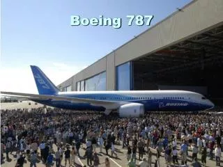
Problem Statement • Design an End Effector • Used to remove or install aircraft components • specific needs provided by Boeing • Boeing has requested our services to build a manipulating end effector • End Effector must connect to existing hoist • Will be used to remove parts for maintenance • The end effector should be capable of translating three inches and rotating 30 degrees in the x, y and z planes.
Key Needs • 6 degrees of freedom • 3 inches of controlled linear movement • Rotational movement of 30 degrees • Lift 100-150 lbs • Weigh less than 250 lbs • Capable of removing/installing components safely • Compatible with existing boom
Design Concepts Conceptual Design #1- Stewart Platform • Design Basics: • Two parallel plates • Six triangulated pistons • Coordinated movements facilitates six degrees of freedom • Universal joints connect the piston to the plates A Stewart Platform basically consists of a base (lower platform) and end effector (top platform) connected by six actuator driven legs.
Design Concepts Conceptual Design #2- Translational Plates • Design Basics: • Power jacks used for translational movement by way of worm gears • Power jacks provide the 3 axis of lateral movement • Rotational movement provided by an arm and piston mechanism
Final Design • Vertical Motion (translational and rotational) is controlled by machine screw jacks. • Translation in Horizontal plane controlled by lead screws and linear bearing. • Last two degrees of rotation controlled by turntables.
Benchmarking • Majority of Metrics and needs met • Strength • Travel and Rotation Distance • Ease of Operation • Translation/Machine Jack Controllability • Some metrics were not fully met: • Turntable Controllability • Volume of End Effector • Weight of End Effector
Manufacturing Report • Manufacturing required basic shop skills • All plates cut using a shear • Drill press used to drill and tap all holes • Welding was done by Norm Martel (in charge of ME student shop) • Minimal Mill and Lathe work was necessary • Materials Used • Hot rolled low carbon steel was used for all plates • Brass ACME lead screws and nuts • All bolts and screws are SAE Grade 5 or higher • Linear bearings made of 10-60 Al with Teflon coated sliders
Bill of Materials/Cost Total Cost: $2,755.30 (Parts only, no labor)
Acknowledgements • Special thanks to the following people who contributed to the successful completion of this project. • Dr. Chuck Pezeshki • Dr. Findley • Kelley Racicot • Alex van Schoonhoven • Alan Cooke • Norm Martel • Jon Grimes • Robert Ames