Download

1 / 23
250 likes | 862 Vues
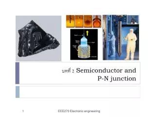
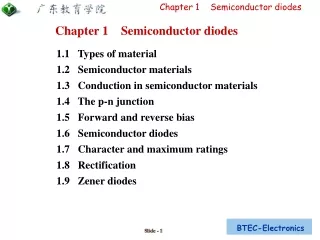
Chapter 1 Semiconductor diodes. 1.1 Types of material 1.2 Semiconductor materials 1.3 Conduction in semiconductor materials 1.4 The p-n junction 1.5 Forward and reverse bias 1.6 Semiconductor diodes 1.7 Character and maximum ratings 1.8 Rectification 1.9 Zener diodes.

E N D
Chapter 1 Semiconductor diodes • 1.1 Types of material • 1.2 Semiconductor materials • 1.3 Conduction in semiconductor materials • 1.4 The p-n junction • 1.5 Forward and reverse bias • 1.6 Semiconductor diodes • 1.7 Character and maximum ratings • 1.8 Rectification • 1.9 Zener diodes
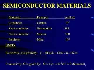
1.1 Types of material ◆Materials may be classified as conductors, semiconduc-conductor, insulators. ◆The classification depends on the value of resistivity of the material. ◆Good conductors are usually metals and have resistivities in the order of 10-7 to 10-8Ωm, ◆semiconductors have resistivities in the order of 10-3 to 103Ωm, ◆the resistivities of insulators are 104 to 1014Ωm,
1.1 Types of material • Conductors: • Aluminium 2.7× 10⁻⁸Ωm • Copper (pure annealed) 1.7× 10⁻⁸Ωm • Semiconductors: (at 27oC) • Silicon 2.3× 10³Ωm • Germanium 0.45 Ωm • Insulators: • Glass > 1010Ωm • PVC > 1013Ωm • Figure 1.1 • variation for a small increase in temperature
1.2 Semiconductor materials • ◆An atom contains bothnegative charge carriers (electrons) and positive chargecarriers (protons).◆Electrons each carry a single unit ofnegativeelectricchargewhileprotonseachexhibitasingleunit of positive charge.◆ Atoms normally contain anequal number of electrons and protons, the net chargepresent will be zero.◆ most semiconductor chips and transistors are created with silicon and germanium. You may have heard expressions like “Silicon Valley” and the “silicon economy”. ◆ If you look "silicon" up in the periodic table, you will find that it sits next to aluminum, below carbon and above germanium. • Figure 1.2
1.2 Semiconductor materials • Figure 1.3 Atomic structure model of silicon and germanium
1.3 Conduction in semiconductor materials • ◆In its pure state, silicon is an insulator because the covalent bonding rigidly holds all of the electrons leaving no free (easily loosened) electrons to conduct current. See figure 1.4. • Figure 1.4 Covalent bond of semiconductor
1.3 Conduction in semiconductor materials • ◆You can change the behavior of silicon and turn it into a conductor by doping it. In doping, you mix a small amount of an impurity into the silicon crystal. • ◆ There are 2 types of doping “N” and “P” • ◆ In N-type doping, phosphorus or arsenic is added to the silicon in small quantities. Phosphorus and arsenic each have five outer electrons, so they're out of place when they get into the silicon lattice. The fifth electron has nothing to bond to, so it's free to move around. Electrons have a negative charge, hence the name N-type. • Figure 1.5 N-type doping semiconductor
1.3 Conduction in semiconductor materials • ◆In P-type doping, boron or gallium is the dopant. Boron and gallium each have only three outer electrons. When mixed into the silicon lattice, they form "holes" in the lattice where a silicon electron has nothing to bond to. The absence of an electron creates the effect of a positive charge, hence the name P-type. Holes can conduct current. A hole happily accepts an electron from a neighbour, moving the hole over a space. • ◆A minute amount of either N-type or P-type doping turns a silicon crystal from a good insulator into a viable (but not great) conductor -- hence the name "semiconductor." • Figure 1.6 P-type doping semiconductor
1.4 The p-n junction • ◆ A p-n junction is a piece of semiconductor material in which part of the material is p-type and part is n-type. • Figure 1.7 The fomation of p-n junction
1.5 Forward and reverse bias • ◆ When an external voltage is applied to a p-n junction making the p-type material positive with respect to the n-type material, the p-n junction is forward biased. • Figure 1.8 forward biased and graphs of the current-voltage relationship
1.5 Forward and reverse bias • ◆ When an external voltage is applied to a p-n junction making the p-type material negative with respect to the n-type material, the p-n junction is reverse biased. • Figure 1.9 reverse biased and graphs of the current-voltage relationship
1.5 Forward and reverse bias • ◆ When an external voltage is applied to a p-n junction making the p-type material negative with respect to the n-type material, the p-n junction is reverse biased. • Figure 1.9 reverse biased and graphs of the current-voltage relationship
1.5 Forward and reverse bias • Figure 11.11 Problem analysis
(a) From Figure 11.11, when V =0.4V, current flowing, • I =1.9mA • (b) When I =9 mA, the voltage dropped across the • diode, V =0.67V • (c) From the graph, when V =0.6V, I =6 mA. • Thus, resistance of the diode • (d) Form the graph the current start at 0.2-0.3V • So it is Germanium
1.5 Forward and reverse bias • Figure 11.13 Problem analysis
1.6 Semiconductor diodes • ◆ A semiconductor diode is an encapsulated p-n junction fitted with connecting leads or tags for connection to external circuitry. • Figure 1.12 Diodes
1.6 Semiconductor diodes • Figure 1.13 Diodes
1.7 Characteristics and maximum ratings • Table 1.1 Characteristicsof some typical signaland rectifier diodes
1.8 Rectification • ◆ The process of obtaining unidirectional currents and voltages from alternating currents and voltages is called rectification. • ◆ Semiconductor diodes are commonly used to convert alternating current (a.c.) to direct current (d.c.), in which case they are referred to as rectifiers. • half-wave rectifier full-wave rectifier • Figure 1.14 Rectifier
1.9 Zener diodes • ◆ Zener diodes are heavily doped silicon diodes that, unlike normal diodes, exhibit an abrupt reverse break down at relatively low voltages (typically less than 6V). • ◆ Zener diodes are available in various families (according to their general characteristics, encapsulations and power ratings) with reverse breakdown (Zener) voltages in the range 2.4V to 91V. • Figure 1.15 graphs of Zener diodes
1.9 Zener diodes • Figure 1.16 Program analysis
When V =−30V, the current flowing in the diode,I=−32.5mA(b) When I =−5 mA, the voltage dropped across thediode, V =−27.5V(c) The characteristic shows the onset of Zener actionat 27V; this would suggest a Zener voltage ratingof 27V(d) Power, P=V ×I, from which, power dissipatedwhen the reverse voltage is 30V,P = 30 × (32.5 × 10−3) = 0.975W = 975mW