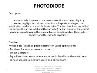
Quadrant Photodiode (QPD)
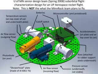
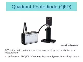
Quadrant Photodiode (QPD). www.thorlabs.com. QPD is the device to track laser beam movement for precise displacement measurement. Reference: PDQ80S1 Quadrant Detector System Operating Manual . Introduction.


Quadrant Photodiode (QPD)
E N D
Presentation Transcript
Quadrant Photodiode (QPD) www.thorlabs.com QPD is the device to track laser beam movement for precise displacement measurement. • Reference: PDQ80S1 Quadrant Detector System Operating Manual
Introduction • Also known as quadrant and bi-cell detectors, these devices have two or four distinct photosensitive elements separated by a minuscule gap. • A light spot illuminating just one element only produces photocurrent in that element. When the spot is translated across the surface of the detector, the energy becomes distributed between adjacent elements. • The ratio between the photocurrent outputs from these elements determines the relative position of the spot on the surface. • It's important to note that the detector only provides position information over a linear distance of the spot diameter. Elsewhere, it is known to be in a specific segment, but not exactly where. Because of this, when working with lasers, defocusing may be required in order to obtain maximum range.
Operating principle Beam incident angle should be normal When the beam is centered on the detector, x, y difference signals come to zero
Trapped Bead Movement Measurement • Measuring lateral displacement with QPD • Irrespective of the particle size we can assume the lateral shift of the particle moves the peak intensity to the cell located in the shift direction. Brownian motion of bead
Con’t • We need to properly set the axial location of the QPD such that the QPD signal is nulled (all quadrants of equal value) irrespective of the location of the spherical particle that coincides with the beam waist center. • Axial displacement can be measured by the change in the power caused by defocusing at the QPD.
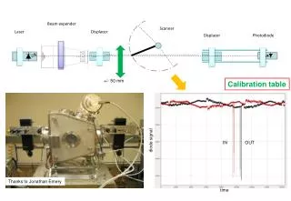
Considerations during QPD calibration Beam selection • Beam shape: QPD is optimized for stablecircular beam • Beam size: 1mm ~ 3.9mm. It depends on sensor area of the device. Minimum diameter should be much larger than the band gap of quadrants. Maximum diameter should be smaller than the half of sensor area. Use lens to control the beam size QPD calibration procedure (manual stage, laser source) 1. Position the beam to the centerofquadrants where x and y difference signals are closely zero. 2. From the center, move the beam to the left until the x difference signal no longer increases and note the value that is negative x limit. 3. Repeat the above step moving the beam to the right of center to determine positive x limit. 4. Repeat step 2 and 3 to determine the positive and negative y limits. 5. Maximum measurement area should not be inclined. If inclined, check the beam is incident with normal to the quadrants. 6. Calculate calibration factor (S/nm) by moving the beam with known distance by using manual stage. Maximum measurement area
QPD API PC API PDQ.h USB.h usb.lib USB communication
Function List and Flow chart • USBinitPDQ80S1(); • PDQSendScanInterval(); • PDQWriteHAlignmentWindow(); • PDQWriteVAlignmentWindow(); • PDQSendScanInterval(); • PDQStartScan(); • PDQReadScan(); • PDQReadScan(); • USBUninit(); USBinitPDQ80S1() PDQSendScanInterval() PDQStartScan() PDQReadScan() Acquisition Complete? N Y PDQStopScan()
QPD (Hamamatsu) QPD is the device to track laser beam movement for precise displacement measurement.
Operating principle Beam incident angle should be normal Dual QPD system (QPD1, QPD2) When the beam is centered on the detector, x, y difference signals come to zero
Circuit of the QPD module • Circuit of the QPD module • D1: QPD sensor • J1: Voltage input of QPD(power supply) • Op-amp (U1~U7) • voltage amplifier with differential inputs • reduce the noise signal • Each signals are calculated in the circuit (X, Y, Sum) • 3 output voltage (J2, J3, J4)
NI DAQ (PCI-6250) • PCI-6250 is a high-speed multifunction M Series data acquisition (DAQ) board optimized for superior accuracy at fast sampling rates • 16 analog inputs, 1 MS/s (Multichannel) • improved measurement accuracy, resolution, and sensitivity by choosing high-accuracy M Series. • PC-BASED DATA ACQUISITION • Libraries for NI DAQ • - DAQmx driver software interactive data-logging software
NI DAQ (SCB-68) • The SCB-68 is a shielded I/O connector block for interfacing I/O signals to plug-in DAQ devices with 68-pin connectors. Combined with the shielded cables, the SCB-68 provides rugged, very low-noise signal termination
NI DAQ (SCB-68) • Connecting the SCB-68 with QPD • AI 0~AI 2 (QPD 1) • AI 0: x signal • AI 1: y signal • AI 2: sum signal • AI 0~AI 5 (QPD 2) • AI 3: x signal • AI 4: y signal • AI 5: sum signal • AI 8~AI 13 • GND (0 volt)
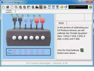
Trapped Bead Movement Measurement • Freq(Hz) : Setting the sampling rate • Duration: Measuring time for QPD • Persistence: Tracking the signal • Start scan: Starting the QPD scan • Start save: Generating text file • Max save count: 6000000
NIDAQmx Functions For QPD Data Aquistion • Task Configuration/Control: DAQmxCreateTask (), DAQmxStartTask(), DAQmxStopTask(), DAQmxClearTask() • Channel Creation: DAQmxCreateAIVoltageChan() • Timing: DAQmxCfgSampClkTiming() • Read: DAQmxReadAnalogF64()
Sample program In project settings, link, “NIDAQmx.lib”