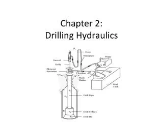
Chapter 2: Drilling Hydraulics
Chapter 2: Drilling Hydraulics. Introduction . One of the primary functions of drilling fluid is to carry drilled cuttings from the bit face, up the annulus, between the drillstring and wellbore, to surface

Chapter 2: Drilling Hydraulics
E N D
Presentation Transcript
Introduction • One of the primary functions of drilling fluid is to carry drilled cuttings from the bit face, up the annulus, between the drillstring and wellbore, to surface • A significant amount of power is required to overcome the (frictional) resistance to flow of the fluid in the drillstring, annulus and through the nozzles in the bit. • The magnitude of the resistance to flow is dependant on a number of variables. • The resistance is expressed in terms of the amount of pressure required to circulate the fluid around the system and is therefore called the circulating pressure of the system.
sacrificial pressure losses: The pressure required to circulate the fluid through the drillstring and annulus are often called sacrificial pressure losses, they do not contribute anything to the drilling process • pressure losses through the nozzles The ejection of the fluid through the nozzles in the bit also results in significant pressure loss but does perform a useful function(it helps to clean the drilled cuttings from the face of the bit.
hydraulic horsepower (HHP) of the pumps • The product of the circulating pressure losses and the flowrate through the system is equal to the hydraulic power that the mud pumps will have to generate. where, Pt = Total pressure (psi) Q = flow rate (gpm) • Since the flowrate through all parts of the system is equal, attention is generally focused on the pressure losses in each part of the system.
This expression for hydraulic horsepower is a general expression and can also be used to express the power which is expended in sacrificial losses and the power that is used to pump the fluid through the nozzles of the bit.
The primary function of the drilling fluid is to carry the drilled cuttings to the surface. In order to do this the velocity of the fluid in the annulus will have to be high enough to ensure that the drilled cuttings are efficiently removed. If these cuttings are not removed the drillstring will become stuck and theoretical optimization will be fruitless. Considerations with respect to optimization should therefore only be addressed once the minimum annular velocity for which the cuttings will be removed is achieved. Only then, should any further increase in fluid flowrate be used to improve the pressure loss across the nozzles of the bit and therefore the hydraulic power at the bit face.
Annular Velocity • This minimum annular velocity is dependent on the properties of the mud and cuttings for any particular well, and is usually between 100 - 200 ft/min
Homework • Assume a flow rate of 920 gpm in a 17.5-inch hole with 4.5-inch drill pipe. What is the annular velocity (ft/min and ft/sec) of the mud?
TRANSPORT VELOCITY • Transport or lift velocity is defined as the difference between the annular velocity of mud and the slip velocity of particle; ie Vt = Va - Vs where Vt = transport velocity Va = annular velocity Dh = hole diameter ODp = outside diameter of pipe
FLOW REGIME • Laminar Flow (Streamline or Viscous flow) : In this type of flow, layers of fluid move in streamlines or laminae. There is no microscopic or macroscopic intermixing of the layers. Laminar flow systems are generally represented graphically by streamlines. • Turbulent Flow : In turbulent flow there is an irregular random movement of fluid in a transverse direction to the main flow. This irregular, fluctuating motion can be regarded as superimposed on the mean motion of the fluid.
FLOW REGIME • Laminar flow: In laminar flow, fluid layers flow parallel to each other in an orderly fashion. This flow occurs at low to moderate shear rates when friction between the fluid and the channel walls is at its lowest. This is a typical flow in the annulus of most wells. • Turbulent flow: This flow occurs at high shear rates where the fluid particle move in a disorderly and chaotic manner and particles are pushed forward by current eddies. Friction between the fluid and the channel walls is highest for this type of flow. This is a typical flow inside the drillpipe and drillcollars. Unlike laminar flow, mud parameters (viscosity and yield point) are not significant in calculating frictional pressure losses for muds in turbulent flow. • Transitional flow : occurs when the fluid flow changes from laminar to turbulent or vice versa.
Determination of the Laminar/Turbulent Boundary in a Newtonian Fluid: • Reynolds showed that when circulating Newtonian fluids through pipes the onset of turbulence was dependant on the following variables: • Pipe diameter, d • Density of fluid, r • Viscosity of fluid, μ • Average flow velocity, v • He also found that the onset of turbulence occurred when the following combination of these variables exceeded a value of 2100 • This grouping of variables is generally termed a dimensionless group and is known as the Reynolds number. In field units:
Types of flow Laminar Turbulent Fig. 4-30. Laminar and turbulent flow patterns in a circular pipe: (a) laminar flow, (b) transition between laminar and turbulent flow and (c) turbulent flow
Rheology • Rheology is a science that uses a combination of mathematical and empirical means. • It attempts to predict the behavior of drilling fluids as they are subjected to the influences of velocity, time, temperature and pressure.
Shear rate • This is a term most applicable to laminar flow. It refers to the change in fluid velocity divided by the width of the channel through which the fluid is flowing in laminar flow.
Shear Stress • The force per unit area required to move a fluid at a given shear rate.
Viscosity • Viscosity is the representation of a fluid’s internal resistance to flow, defined as the ratio of shear stress to shear rate. Viscosity is expressed in poise. • A poise is a very large number and therefore, viscosity is typically reported in centipoise • (100 centipoise = 1 poise).
Rheological Models Newtonian Bingham Plastic Power-Law
Newtonian Fluid Model In a Newtonian fluid the shear stress is directly proportional to the shear rate (in laminar flow): i.e., The constant of proportionality, is the viscosity of the fluid and is independent of shear rate.
Laminar Flow of Newtonian Fluids Experimentally:
Newtonian Fluid Model Viscosity may be expressed in poise or centipoise.
. Shear Stress vs. Shear Rate for a Newtonian Fluid Slope of line = m
Apparent Viscosity Apparent viscosity = is the slope at each shear rate,
(Plotted on linear paper) Typical Drilling Fluid Vs. Newtonian, Bingham and Power Law Fluids 0
Rheological Models 1. Newtonian Fluid: 2. Bingham Plastic Fluid: What ifty = 0?
API Power Law Model API RP 13D K = consistency index n = flow behaviour index 0
API Power Law Model • It describes the thickness or pumpability of the fluid, and is somewhat analogous to the apparent viscosity. • The flow behavior index (n) indicates the degree of non-Newtonian characteristics of the fluid. • As the fluid becomes more viscous, the consistency factors (k) increases; as a fluid becomes more shear thinning “n” decreases. When “n” is 1 the fluid is Newtonian. • If “n” is greater than 1, the fluid is classed as Dilatant (the apparent viscosity increases as the shear rate increases). • If “n” is between zero and 1 the fluid is classified as Pseudoplastic, exhibiting shear-thinning; (i.e., the apparent viscosity decreases as the shear rate increases). • For drilling fluids, this is a desirable property and most drilling fluids are pseudoplastics.
Table 4.3 - Summary of Equations for Rotational Viscometer or Newtonian Model
Bingham Plastic Model Table 4.3 - Summary of Equations for Rotational Viscometer or or
Frictional Pressure Drop In Pipes and Anuli When attempting to quantify the pressure losses inside the drillstring and in the annulus it is worth considering the following matrix:
Critical velocity • Critical velocity inside drill pipes and drill collars: • Critical velocity inside annulus:
Laminar Flow in Pipes and Annuli • The flow regime within which the fluid is flowing in a pipe or annulus will depend on the Reynolds number for the system in question. • The Reynolds number for each part of the system will however be different and it is possible for the fluid in one part of the system to be in laminar flow and the other in turbulent flow.
Laminar Flow in Pipes and Annuli (cont’d) • Hence the fluid may be in laminar flow in the drillpipe but in turbulent flow in the drillcollars. • The equations which describe the pressure losses when the fluid is in laminar flow can be derived theoretically.
Laminar Flow in Pipes and Annuli (cont’d) • Equation for the pressure loss for the flow of a Newtonian Fluid in a pipe: • Equation for the flow of Newtonian Fluid in an annulus can be derived:
Laminar Flow in Pipes and Annuli (cont’d)Bingham Plastic Fluids • The equation for the frictional pressure loss in a pipe whilst circulating a Bingham Plastic Fluid is given by • The equation for the frictional pressure loss in an annulus whilst circulating a Bingham Plastic Fluid is given by :
Laminar Flow in Pipes and Annuli (cont’d) Power Law Fluid • The equation for the frictional pressure loss in a pipe whilst circulating a Power law Fluid is given by : • The equation for the frictional pressure loss in an annulus whilst circulating a Power law Fluid is given by :
Example:Pressure loss in Laminar Flow Calculate the velocity of a fluid flowing through a 5" 19.5 lb/ft drillpipe (I.D.= 4.276") at 150 gpm. b. Determine the pressure loss in the above situation if the fluid is a Bingham Plastic fluid with a plastic viscosity of 20 cp, a yield point of 15 lb/100 sq. ft and density is 10 ppg. c. Calculate the pressure loss in the above situation if the fluid was a Power Law fluid with an non-Newtonian Index of 0.75 and a consistency index of 70 eq cp
Solution b. If the fluid in the above situation is a Bingham Plastic fluid with a plastic viscosity of 20 cp, a yield point of 15 lb/100 sq. ft and density is 10 ppg the pressure loss in the pipe will be: a. The velocity of a fluid flowing through a 5" 19.5 lb/ft drillpipe (I.D. = 4.276") at 150 gpm is:
c. The pressure loss in the above situation if the fluid was a Power Law fluid with an non-Newtonian Index of 0.75 and a consistency index of 70 eq cp would be:
Turbulent Flow • When the drilling fluid is pumped at a high rate the fluid laminar become unstable and break into a chaotic, diffused flow pattern. The fluid is then in turbulent flow.
Turbulent Flow of Newtonian Fluids in PipesThe equation for the pressure losses in turbulent flow of a Newtonian fluid in a pipe is derived from incorporating a control factor in the pressure loss equation: • This equation is known as the Fanning Equation and the friction factor, f defined by this equation is called the Fanning friction factor. All of the terms in this equation, except for the friction factor, can be determined from the operating parameters. • The friction factor, f is a function of the Reynolds Number NRe and a term called the relative roughness, e/d.
Fanning chart • A plot of friction factor against Reynolds number on log-log paper is called a Fanning chart: