Pipelining Overview
This document provides an overview of computer architecture pipelining, discussing concepts like the single cycle and multi-cycle instruction execution. Key topics include instruction fetching, decoding, execution, memory access, and write-back stages. Pipelining is examined in detail through visual diagrams that illustrate the flow of instructions across multiple stages, emphasizing how it improves throughput while maintaining execution time constraints. Additionally, the document addresses the drawbacks of single-cycle processors and the benefits of adopting a pipelined approach.

Pipelining Overview
E N D
Presentation Transcript
Pipelining Overview Computer Science 104
Admin • Homework 6 due Wed Dec 4 • Final Saturday Dec 14, 2pm – 5pm
31 26 21 16 0 op rs rt immediate Review: The Single Cycle Datapath during Branch • if (R[rs] - R[rt] == 0) then Zero <- 1 ; else Zero <- 0 Instruction<31:0> Branch = 1 Instruction Fetch Unit Jump = 0 Rd Rt <21:25> <16:20> <11:15> <0:15> Clk RegDst = x 1 0 Mux ALUctr = Subtract Rt Rs Rd Imm16 Rs Rt RegWr = 0 MemtoReg = x 5 5 5 busA Zero MemWr = 0 Rw Ra Rb busW 32 32 32-bit Registers 0 ALU 32 busB 32 0 Clk Mux 32 Mux 32 1 WrEn Adr 1 Data In 32 Data Memory Extender imm16 32 16 Clk ALUSrc = 0 ExtOp = x
. . . . . . op<5> op<5> op<5> op<5> op<5> op<5> . . . . . . <0> <0> <0> <0> <0> op<0> R-type ori lw sw beq jump Review: Implementation of the Main Control RegWrite ALUSrc RegDst MemtoReg MemWrite Branch Jump ExtOp ALUop<2> ALUop<1> ALUop<0>
Putting it All Together: A Single Cycle Processor ALUop ALU Control ALUctr 3 RegDst func op 3 Main Control Instr<5:0> 6 ALUSrc 6 : Instr<31:26> Instruction<31:0> Branch Instruction Fetch Unit Jump Rd Rt <21:25> <16:20> <11:15> <0:15> Clk RegDst 1 0 Mux Rt Rs Rd Imm16 Rs Rt RegWr ALUctr 5 5 5 MemtoReg busA Zero MemWr Rw Ra Rb busW 32 32 32-bit Registers 0 ALU 32 busB 32 0 Clk Mux 32 Mux 32 1 WrEn Adr 1 Data In 32 Data Memory Extender imm16 32 16 Instr<15:0> Clk ALUSrc ExtOp
Worst Case Timing: lw $1, $2(offset) Clk Clk-to-Q Old Value New Value PC Instruction Memoey Access Time Rs, Rt, Rd, Op, Func Old Value New Value Delay through Control Logic ALUctr Old Value New Value ExtOp Old Value New Value ALUSrc Old Value New Value MemtoReg Old Value New Value Register Write Occurs RegWr Old Value New Value Register File Access Time busA Old Value New Value Delay through Extender & Mux busB Old Value New Value ALU Delay Address Old Value New Value Data Memory Access Time busW Old Value New
Drawback of this Single Cycle Processor • Long cycle time: • Cycle time must be long enough for the load instruction: PC’s Clock -to-Q + Instruction Memory Access Time + Register File Access Time + ALU Delay (address calculation) + Data Memory Access Time + Register File Setup Time + Clock Skew • Cycle time is much longer than needed for all other instructions • What we want is to break the execution of a single instruction into multiple steps
Key Metric for Processor Architecture • Execution Time= Seconds/Program = Instructions/program * Cycles/Instruction * Seconds/Cycle • Which things affect the three terms? • Algorithm, • Instruction Set Architecture, • Implementation (microarchitecture & circuits)
Break Instructions in Multiple Cycles • The root of the single cycle processor’s problems: • The cycle time has to be long enough for the slowest instruction • Solution: • Break the instruction into smaller steps • Execute each step (instead of the entire instruction) in one cycle • Cycle time: time it takes to execute the longest step • Keep all the steps so they have similar length • Cycle time is much shorter
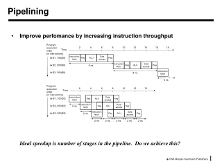
Ifetch Reg/Dec Exec Mem WrB The Five Stages of Load Cycle 1 Cycle 2 Cycle 3 Cycle 4 Cycle 5 • Ifetch: Instruction Fetch • Fetch the instruction from the Instruction Memory • Reg/Dec: Registers Fetch and Instruction Decode • Exec: Calculate the memory address • Mem: Read the data from the Data Memory • WrB: Write the data back to the register file Load
The Five Steps of a Load Instruction Instr Decode / Reg Fetrch Instruction Fetch Address Data Memory Reg Wr Clk Clk-to-Q Old Value New Value PC Instruction Memory Access Time Rs, Rt, Rd, Op, Func Old Value New Value Delay through Control Logic ALUctr Old Value New Value ExtOp Old Value New Value ALUSrc Old Value New Value RegWr Old Value New Value Register File Access Time busA Old Value New Value Delay through Extender & Mux Register File Write Time busB Old Value New Value ALU Delay Address Old Value New Value Data Memory Access Time busW Old Value New
Key Ideas Behind Instruction Execution Pipelining • Overlap execution of instructions • The load instruction has 5 stages: I-fetch,Reg- Fetch / I-Decode, Execute, Memory-Access, Register Write-Back. • Five independent functional units to work on each stage • Each functional unit is used only once • The 2nd load can start as soon as the 1st finishes its Ifetch stage • Each load still takes five cycles to complete. latency is still 5 cycles • The throughput is much higher. • Instructions start before the previous ones are completed.
1st lw Ifetch Reg/Dec Exec Mem WrB Ifetch Reg/Dec Exec Mem WrB Ifetch Reg/Dec Exec Mem WrB Pipelining the Load Instruction (Pipeline Diagram) Cycle 1 Cycle 2 Cycle 3 Cycle 4 Cycle 5 Cycle 6 Cycle 7 Clock • The five independent functional units in the pipeline datapath are: • Instruction Memory for the Ifetch stage • Register File’s Read ports (bus A and busB) for the Reg/Dec stage • ALU for the Exec stage • Data Memory for the Mem stage • Register File’s Write port (bus W) for the WrB stage • One instruction enters the pipeline every cycle • One instruction comes out of the pipeline (completed) every cycle • The “Effective” Cycles per Instruction (CPI) is 1; ~1/5 cycle time 2nd lw 3rd lw
Ifetch Reg/Dec Exec WrB The Four Stages of R-type Cycle 1 Cycle 2 Cycle 3 Cycle 4 • Ifetch: Instruction Fetch • Fetch the instruction from the Instruction Memory • Reg/Dec: Register acces and Instruction Decode • Exec: ALU operates on the two register operands • WrB: Write the ALU output back to the register file R-type
Ifetch Reg/Dec Exec Wr Ifetch Reg/Dec Exec Wr Ifetch Reg/Dec Exec Mem Wr Ifetch Reg/Dec Exec Wr Ifetch Reg/Dec Exec Wr Pipelining the R-type and Load Instruction Cycle 1 Cycle 2 Cycle 3 Cycle 4 Cycle 5 Cycle 6 Cycle 7 Cycle 8 Cycle 9 Clock • We have a problem:Two instructions try to write to the register file at the same time! • This is called a structural hazard. OOPS! We have a problem! R-type R-type Load R-type R-type
1 2 3 4 5 Load Ifetch Reg/Dec Exec Mem WrB 1 2 3 4 R-type Ifetch Reg/Dec Exec WrB Important Observation • Each functional unit can only be used once per instruction • Each functional unit must be used in the same stage for all instructions: • Load uses Register File’s Write Port during its 5th stage • R-type uses Register File’s Write Port during its 4th stage • How to solve this pipeline hazard?
Ifetch Reg/Dec Wr Ifetch Reg/Dec Exec Mem WrB Ifetch Reg/Dec Exec Mem WrB Ifetch Reg/Dec Exec Mem WrB Ifetch Reg/Dec Exec Mem WrB Ifetch Reg/Dec Exec Mem WrB Solution: Delay R-type’s Write by One Cycle (Stall) • Delay R-type’s register write by one cycle: • Now R-type instructions also use Reg File’s write port at Stage 5 • Mem stage is a NO-OPstage: nothing is being done. Effective CPI? 1 2 3 4 5 R-type Exec Mem Cycle 1 Cycle 2 Cycle 3 Cycle 4 Cycle 5 Cycle 6 Cycle 7 Cycle 8 Cycle 9 Clock R-type R-type Load R-type R-type
Pipeline Control • Need to propagate Datapath control along with instructions • Pipeline control is logic to control movement along pipeline (including datapath control)
1 Mux 0 A Pipelined Datapath Clk Ifetch Reg/Dec Exec Mem WrB ExtOp ALUOp Branch RegWr 1 0 PC+4 PC+4 Imm16 PC PC+4 Imm16 Data Mem Rs Zero busA A Ra busB Exec Unit RA Do Rb IUnit IF/ID Register Ex/Mem Register Mem/Wr Register ID/Ex Register Rt WA RFile Di Rw Di Rt 0 I Rd 1 ALUSrc RegDst MemWr MemtoReg
Cycle 1 Cycle 2 Cycle 3 Cycle 4 Cycle 5 Cycle 6 Cycle 7 Cycle 8 Clock 0: Load Ifetch Reg/Dec Exec Mem WrB 4: R-type Ifetch Reg/Dec Exec Mem WrB 8: Store Ifetch Reg/Dec Exec Mem WrB 12: Beq (target is 1000) Ifetch Reg/Dec Exec Mem WrB End of Cycle 4 End of Cycle 5 End of Cycle 6 End of Cycle 7 A More Extensive Pipelining Example • End of Cycle 4: Load’sMem, R-type’s Exec, Store’s Reg, Beq’s Ifetch • End of Cycle 5: Load’sWrB, R-type’s Mem, Store’s Exec, Beq’sReg • End of Cycle 6: R-type’sWrB, Store’sMem, Beq’sExec • End of Cycle 7: Store’sWrB, Beq’sMem
Data Dependcies • So far we ignored instructions dependencies, but in a real machine one must deal with dependencies. • A data dependence is when an instruction source operand is the destination operand of a previous instruction. • Example: sub$2, $1, $3 and $12, $2, $5# $12 depends on the result in $2 or $13, $6, $2 # but $2 is updated 3 clock add $14, $2, $2 # cycles later. sw $15, 100($2)# We have a problem!!
Ifetch Reg/Dec Exec Mem WrB Ifetch Reg/Dec Exec Mem WrB Ifetch Reg/Dec Exec Mem WrB Ifetch Reg/Dec Exec Mem WrB Ifetch Reg/Dec Exec Mem WrB Data Hazards • So far we ignored instructions dependencies, but in a real machine one must deal with dependencies. • Example: sub$2, $1, $3 and $12, $2, $5# $12 depends on the result in $2 or $13, $6, $2 # but $2 is updated 3 clock add $14, $2, $2 # cycles later. sw $15, 100($2)# We have a problem!! Cycle 1 Cycle 2 Cycle 3 Cycle 4 Cycle 5 Cycle 6 Cycle 7 Cycle 8 Clock 0: sub 4: and 8: or 12: add 16: sw
Ifetch Reg/Dec Exec Mem WrB Ifetch Reg/Dec Exec Mem WrB Ifetch Reg/Dec Exec Mem WrB Ifetch Reg/Dec Exec Mem WrB Ifetch Reg/Dec Exec Mem WrB Stall to Avoid Hazards • Modify pipeline control to delay execution of an instruction if source operands not available Cycle 1 Cycle 2 Cycle 3 Cycle 4 Cycle 5 Cycle 6 Cycle 7 Cycle 8 Clock 0: sub 4: and 8: or 12: add 16: sw
Ifetch Reg Exec Mem Wr Single Cycle, Multiple Cycle, vs. Pipeline Cycle 1 Cycle 2 Clk Single Cycle Implementation: Load Store Waste Cycle 1 Cycle 2 Cycle 3 Cycle 4 Cycle 5 Cycle 6 Cycle 7 Cycle 8 Cycle 9 Cycle 10 Clk Multiple Cycle Implementation: Load Store R-type Ifetch Reg Exec Mem Wr Ifetch Reg Exec Mem Ifetch Pipeline Implementation: Load Ifetch Reg Exec Mem Wr Store Ifetch Reg Exec Mem Wr R-type
The Five Steps of a Load Instruction Instr Decode / Reg Fetrch Instruction Fetch Address Data Memory Reg Wr Clk Clk-to-Q Old Value New Value PC Instruction Memory Access Time Rs, Rt, Rd, Op, Func Old Value New Value Delay through Control Logic ALUctr Old Value New Value ExtOp Old Value New Value ALUSrc Old Value New Value RegWr Old Value New Value Register File Access Time busA Old Value New Value Delay through Extender & Mux Register File Write Time busB Old Value New Value ALU Delay Address Old Value New Value Data Memory Access Time busW Old Value New
Ifetch Rfetch/Decode BrComplete ALUOp=Add 1: PCWr, IRWr ALUOp=Add ALUOp=Sub x: PCWrCond 1: BrWr, ExtOp ALUSelB=01 RegDst, Mem2R ALUSelB=10 x: IorD, Mem2Reg Others: 0s RegDst, ExtOp x: RegDst, PCSrc IorD, MemtoReg 1: PCWrCond ALUSelA Others: 0s PCSrc RExec 1: RegDst ALUSelA ALUOp=Or ALUSelB=01 1: ALUSelA ALUOp=Rtype ALUSelB=11 x: PCSrc, IorD MemtoReg x: MemtoReg ExtOp IorD, PCSrc Rfinish 1: ALUSelA ALUOp=Rtype ALUOp=Or RegWr, ExtOp 1: RegDst, RegWr MemtoReg x: IorD, PCSrc ALUselA ALUSelB=11 ALUSelB=11 ALUSelB=01 ALUOp=Add 1: ALUSelA x: IorD, PCSrc x: PCSrc RegWr ExtOp IorD Initial Representation: Finite State Diagram 0 1 8 Wait beq 2 AdrCal 1: ExtOp ALUSelA ALUSelB=11 lw or sw ALUOp=Add x: MemtoReg Wait Ori PCSrc 10 Rtype lw sw OriExec 3 6 5 SWMem LWmem 1: ExtOp ALUSelA, IorD 1: ExtOp MemWr ALUSelB=11 ALUSelA ALUOp=Add ALUSelB=11 x: MemtoReg ALUOp=Add PCSrc x: PCSrc,RegDst 11 MemtoReg OriFinish 7 4 LWwr
Pipelining Summary • Most modern processors use pipelining • Pentium 4 has 24 (35) stage pipeline! • Intel Core 2 duo has 14 stages • Alpha 21164 has 7 stages • Pipelining creates more headaches for exceptions, etc… • Pipelining augmented with superscalar capabilities