Download

1 / 34
340 likes | 358 Vues
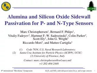
Alumina and Silicon Oxide Sidewall Passivation for P- and N-Type Sensors. Marc Christophersen 1 , Bernard F. Phlips 1 , Vitaliy Fadeyev 2 , Hartmut F.-W. Sadrozinski 2 , Colin Parker 2 , Scott Ely 2 , John G. Wright 2 Riccardo Mori 3 , and Matteo Cartiglia 3

E N D
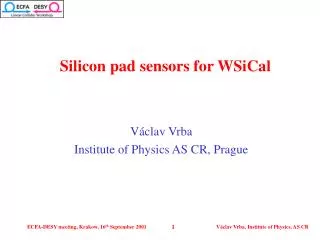
Alumina and Silicon Oxide Sidewall Passivation for P- and N-Type Sensors • Marc Christophersen1, Bernard F. Phlips1, • Vitaliy Fadeyev2, Hartmut F.-W. Sadrozinski2, Colin Parker2, Scott Ely2, John G. Wright2 • Riccardo Mori3, and Matteo Cartiglia3 • Code 7654, U.S. Naval Research Laboratory; • Santa Cruz Institute for Particle Physics (SCIPP), UCSC; • (3) University of Florence, Italy • Contact: marc.christophersen@nrl.navy.mil • +1-202-404-2448
Outline • Slim Edges – Motivation and Approach • Type of Sidewall Passivation and Edge Damage • Results for P-Type Sensors • - Alumina for P-Type Silicon Passivation • - IV Curves for P-Type Diodes with Alumina Passivation • - Charge Collection Measurements • Results for N-Type Sensors • - PECVD Oxide and Nitride Passivations • - IV Curves for N-Type Sensors • - Large Area Sensors • Conclusions and Outlook
Motivation – Slim Edges strips active area slim edge guard rings inactive area Optical micrograph If you obtain minimal damage at edge and “right” sidewall surface charge one can make slim edges with post processing. • Slim edges offer: • better tiling of sensors • reduced inactive area
Type of Sidewall Passivation – N-Type Si oxidized trench n-type (10k Wcm) n-type (10k Wcm) inactive region inactive region • A passivated trench with a thermally grown oxide (positive charge density 1011 cm-2) trench will lead to [idea from J. D. Segal and C. J. Kenney, IEEE NSS 2010]: • control potential drop toward the cut edge, • protection from saw cut edge.
Type of Sidewall Passivation – P-Type Si n-strip alumina 0 -40 -112 -145 p-type (20k Wcm) Negative charge (-1E11 cm-2) • Alumina passivation, negative interface charge ~ -1013 cm-2, leads to: • high electric field strip edge, • partially controlled potential drop towards the cut edge.
Fabrication Sequence finished die Laser-cutting or XeF2-scribing and cleaving (see detailed slides) Al2O3 ALD at 300 ºC annealing at 400 ºC RIE with hard mask The process sequence is analogous for n-type Si but the ALD deposition is replaced by SiO2 and Si3N4 PECVD (plasma enhanced chemical vapor deposition).
Edge Scribing and Cleaving • used finished dies (post-processing) • laser scribing only at edge → no laser damage near active area • most separation is done by pure cleaving → no sidewall damage Optical micrograph, top-view Optical micrograph, top-view after cleaving after cleaving Cleaving is still done by hand using tweezers, but can be done automatically. tweezers
P-Type Diodes Device A 14 mm • slim edge • no guard ring • die level processing cleaved edge diode edge Device B Si diode Processed device with alumina layer guard ring Un-processed reference SiO2
Charge Collection – P-Type Strip Sensor • Consistent beam profiles taken at different positions is an indication of high efficiency at the edge. • By scanning the thresholds we can derive the collected charge on each strip. • We observe the same collected charge at all locations to a few percent.
N-Type Diodes PECVD oxide and nitride passivation GLAST test diodes • Applying the same method to n-type using a positive sidewall passivation: • PECVD (plasma enhanced chemical vapor deposition), • variation in deposition temperature and material (next slide).
N-Type Diodes GLAST test diode Silicon nitride side wall passivations shows lowest leakage currents for n-type sensors.
Analysis of GLAST Skinny Signal: Cut/Un-Cut Cut Un-cut Vbias=150V, ~100 nA. Vbias=500V (200 V efficient). ~15 uA Charge collection tests with Beta particles performed at U. of Florence. Charge collection profile is unchanged. .
Large Area Sensors 8 mm • CIS strip sensor from PPS submission. • 8-guard ring design originally from Liverpool. SEMI standard for flat/crystal alignment: +/- 0.9 degrees typical values for FZ material: +/- 0.1 degrees Cleaving is easier if • device aligned with <100> direction, • no mechanical stress from thin films. BUT pure cleaving is not practical for large sensors!
XeF2 Etching • XeF2 vapor phase etching exhibits nearly infinite selectivity of silicon to photo-resist, polymers, SiO2, Si3N4, and aluminum -- ideal for processing finished sensors. • Being a vapor phase etchant, XeF2 avoids many of the problems typically associated with wet processes. • XeF2 etch introduces no mechanical stress or heat effect zone.
“XeF2-Scribing” and Cleaving • used finished dies (post-processing) • laser scribing only at edge → no laser damage near active area • cleaving → no sidewall damage • very shallow XeF2 etch will guide cleavage plane (details next slides) Optical micrograph, top-view SEM micrograph, cross-section before cleaving after cleaving Cleaving is still done by hand using tweezers, but can be done automatically. tweezers
XeF2 Etching after cleaving guard ring laser damage cleavage plane SEM micrographs (bird’s-eye view)
Large Area Sensors Optical micrograph, top view • GLAST Baby sensor (1.5 x 3 cm) • cut distance to guard 50 mm
Large Area Sensors Si3N4 sidewall passivation deposition done at 300 ºC • GLAST Baby sensor (1.5 x 3 cm) • XeF2 scribing through guard • cut distance to “jog-outs” from bias ring ~ 20 mm Optical micrograph, top view
Conclusions and Future Work • Cleaved sidewall hasnosilicon damage. • P-type silicon requires negative side wall passivation. • Alumina/silicon interface has negative charge. • N-type silicon requires positiveside wall passivation • Excellent charge collection for p-type Si with alumina sidewall passivation. • Silicon nitride sidewall passivation shows lowest leakage current for n-type Si. • Large area sensor by cleaving along a shallow XeF2 etched groove. • Find alternative to manual cleaving using tweezers (ongoing). • Determine exact alumina/silicon interface charge (CV plots). • Alumina surface charge region sensitive to radiation/dose (ongoing)?
Laser-Scribing and Cleaving • used finished dies (post-processing) • laser scribing → less laser damage → lower leakage currents • cleaving → no damage Optical micrograph, top-view SEM micrograph, cross-section Laser-cut Laser-scribing done at U.S. Naval Research Laboratory using an Oxford Laser Instruments E-Series tool. Cleaving done by hand using tweezers, but can be done automatically. tweezers
SiO2 – Si Interface Charges SiO2 x Qf – fixed + + + + + + SiOx x x x x x x x x x x x x y Qt – interface (trapped charges and traps) Si Properties of sidewall passivation for HEP sensors: • low recombination rate for sidewall passivation → high carrier life time, low trap density at interface • fixed interface charge (positive for n-type Si) • low temperature process for processing finished dies. • “Origin” of excellent passivation for n-type Si: • Thermally grown oxides typically have from ~ 1010 to 1-2x10¹¹positivecharges per cm2. • surface recombination rate: FZ n-type Si (10 Wcm): ~ 60 cm/s.
Analysis of GLAST Skinny sensor: cut/un-cut Cut Un-cut Distribution: sigma=4.7ADCs. Vbias=500V. Distribution: sigma=4.7ADCs Vbias=150V. No noise increase due to laser cutting.
Aside – Alumina as an Effective P-Stop strip 1 • Inter-strip shortening due to electron accumulation is a problem for any segmented p-type and double-sided n-type detectors. • ALD deposited alumina acts as an effective p-stop for n- and p-type Si substrates (U.S. patent pending). • We successfully fabricated a double sided strip detector (DSSD) on n-type Si with alumina as an effective p-stop for n-on-n strips. • DSSD was tested under gamma-ray irradiation (~ 6 keV FWHM energy resolution at 122 keV). strip 2 oxide + + + + + + + + n+ n+ p-stop electron layer p- substrate p+ backplane strip 1 strip 2 alumina ---------- n+ n+ p- substrate p+ backplane Details given in 2011 IEEE NSS presentation by M. Christophersen
Industrial Applications of Laser-Scribing & Cleaving • laser-scribing and cleaving common in LED industry • automated tools for scribing and breaking of devices on wafer-scale
“6th Trento Workshop”,March 2-4, 2011 Laser-Scribing & Al2O3 Sidewall Passivation of P-Type Sensors Similar in chemistry to CVD (chemical vapor deposition), except that the ALD (atomic layer deposition) reaction breaks the CVD reaction into two half-reactions, keeping the precursor materials separate during the reaction. ALD film growth is self-limited and based on surface reactions, which makes achieving atomic scale deposition control possible. Perfect 3-D conformality, 100% step coverage: uniform coatings on flat, inside porous and around particle samples. Origin of negative interface charge: Functional surface groups on the silicon wafer are not optimal for an adsorption of the TMA (trimethylaluminium) precursor molecules, which leads to an incomplete reaction of the TMA and, consequently, an increased relative oxygen concentration at the interface (F. Werner et al.,25th European Photovoltaic Solar Energy Conference, Valencia, Spain, 6-10 September 2010). Introduction - ALD
Equilibrium Electron-Concentrations for SiO2 and Al2O3 n-strip n-strip silicon oxide alumina p-type (20k Wcm) p-type (20k Wcm) Positive charge (+1E11 cm-2), no bias (V=0) Negative charge (-1E11 cm-2), no bias (V=0) • silicon oxide electrons path from n-strip to sidewall • alumina electrons “pushed away” from sidewall
Slim Edges - Approaches J. D. Segal, et al., NSS 2010 A. Rummler et al., 2010 E. Verbitskaya et al., 13 RD 50 workshop, 2008 J. Kalliopuska, NSS 2010 T.-E. Hansen et al., 2009 • Goal of our research: • slim edges with finished devices on die level • slim edges on p- and n-type devices
Negative Surface Charge for P-Type Passivation Surface recombination rate for FZ p-type Si (2 Wcm), Al2O3 passivation ALD – Atomic Layer Deposition thermal SiO2 n-type @ 400 °C Data from G. Dingemans, et al., 35th IEEE PVSC 2010. • low recombination rate after Al2O3 passivation → high carrier life time • detector material kWcm → higher life times • fixed negative interface charge • low temperature process (< 400 °C) • standard process in solar cell industry Negative interface charge enables effective surface passivation for p-type Si. Values for surface recombination rate and charge density for Al2O3 /p-type Si are comparable to SiO2/n-type Si.
Type of Sidewall Passivation and Edge Damage • slim edge • no guard ring • die level processing • p-type diode If you obtain minimal damage at edge and “right” sidewall surface charge one can make slim edges with post processing. Data taken from 6th Trento Workshop presentation, March 2011
Oxidized Trench for P-Type Si n-strip p-type (10k Wcm) high electric field strength • An oxidized trench leads to: • high electric field at trench edge, • no control potential drop toward the cut edge, • no protection from saw cut edge.
XeF2 Etching after cleaving before cleaving cleavage plane Optical micrograph (top view) SEM micrograph (bird’s-eye view) • XeF2 etch generates very shallow trench. • Trench “guides” cleavage plane. • No mechanical stress or localized heating.
Acknowledgements We would like to thank the Institute for Nanoscience (NSI) at the Naval Research Laboratory (NRL) and the NSI staff members. This work was funded in part by the Office of Navy Research (ONR).