Reconstructing Building Interiors from Images
180 likes | 194 Vues
This project focuses on using images to reconstruct 3D models of building interiors. It addresses challenges such as texture-poor surfaces and visibility reasoning. The pipeline includes steps for 3D location, surface normal estimation, and generating hypothesis planes.

Reconstructing Building Interiors from Images
E N D
Presentation Transcript
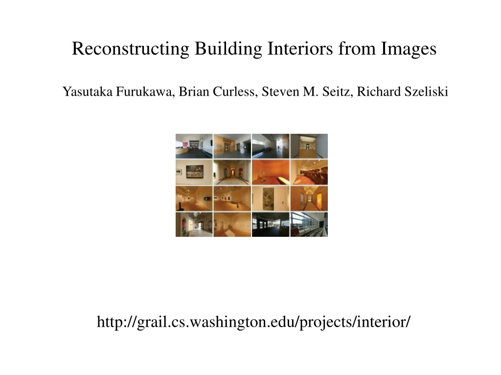
Reconstructing Building Interiors from Images Yasutaka Furukawa, Brian Curless, Steven M. Seitz, Richard Szeliski http://grail.cs.washington.edu/projects/interior/
Motivation (or why another MVS algorithm for interiors?) • Texture Poor Surfaces • Visibility reasoning • Scalability Challenge 1 3 2
3D Reconstruction Pipeline • 3D Location • Surface Normal • Set of Visible images Vi ={I1, I2, …..}
Manhattan-World Stereo Yasutaka Furukawa, Brian Curless, Steven M. Seitz http://grail.cs.washington.edu/projects/manhattan/ Output : Depth map for each individual image Step 1: (Oriented Points –Input) • 3D Location • Surface Normal • Set of Visible images Vi ={I1, I2, …..}
Step 2: (Dominant Axes Extraction) • Only approximately orthogonal • Histogram of the surface normals from STEP 1 • Appropriately declare the largest bins as dominant axes. , and So now we have
Step 3: (Generating Hypothesis planes) Calculate offsets For each k=1,2,3 and all Pi from STEP 1 on Mean Shift Clustering: to identify peak density areas Ouput : Set of Hypothesis planes
Mean shift clustering Data Set: X={x1, x2, …….. xn} For each x in X 1. Calculate where Is a Gaussian kernel 2. Shift x to m(x). 3. Repeat steps 1 to 3 until x converges to m(x) D. Comaniciu and P. Meer. Mean shift: A robust approach toward feature space analysis. IEEE:PAMI, 24(5):603–619, May 2002.
Step 4(final): Labeling each pixel with a plane The labeling problem: Label each pixel with a hypothesis plane Smoothness term Data term
Data term Conflicts:
Smoothness term We make use of priors (evidence) here : edges
We are here with a depth map for each input image MRF models and solving them using graph cuts 1. Boykov, Y., Kolmogorov, V., An Experimental Comparison of Min-Cut/Max-Flow Algorithms for Energy Minimization in Vision, In IEEE Transactions on PAMI, Vol. 26, No. 9, pp. 11241137, 2004 2.Graph cut matching in Computer Vision, Toby Colbins
Volumetric Reconstruction • A labeling problem again… • We label each voxel as either • ‘interior’ or ‘exterior’ Smoothness term Data term Data term We make each depth map vote for a voxel
Notations: Pv V • If v is behind pv, then it is labeled interior. • If v is in the front of pv, it is exterior. • We ask each depth map for a given voxel. • The depth map may vote a voxel as interior, exterior or empty(no visibility). • Majority wins. Corner case: What if a depth map votes the voxel as empty? We take it as a vote for exterior.
Smoothness term Why, no priors? Because, there is nothing left to encode. The energy minimum is not unique
Now we have labeled each voxel as interior or exterior. Delaunay triangulation Delaunay triangulations maximize the minimum angle of all the angles of the triangles in the triangulation; they tend to avoid skinny triangles.
Identify boundaries between exterior and interior voxel regions. • Hence identify connected components in the voxel grid. • 3. For each connected component in a vertical slice, • perform a Delaunay triangulation We get a mesh model out of this.
A list of optimizations before we get the 3D model 1. Grid Pruning: Remove a couple of grid slices. We want grid slices to pass through “grid pixels”. 2. Ground Plane determination: The system has very little idea of the ground. The bottom most horizontal slice with a lot of “grid pixels” Or the bottom most slice with a count greater than the average. 3. Boundary filling