Download
1 / 14
140 likes | 164 Vues
EMT 354-Photonic Devices Chapter 2.3. Coupler. Photonic Devices - Couplers. Optical fibre couplers. A basic photonic device used to split or combine light to or from different fibres. A building block of “passive optical networks”. Photonic Devices - Couplers. Optical Couplers.

E N D
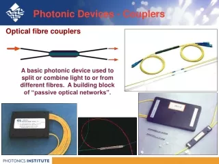
Photonic Devices - Couplers Optical fibre couplers A basic photonic device used to split or combine light to or from different fibres. A building block of “passive optical networks”.
Optical Couplers • Optic couplers either split optical signals into multiple paths or combine multiple signals on one path. • The number of input (N)/ output (M) ports, (i.e.s N x M size) characterizes a coupler. • Fused couplers can be made in any configuration, but they commonly use multiples of two (2 x 2, 4 x 4, 8 x 8, etc.).
Coupler • Uses • Splitter: (50:50) • Taps: (90:10) or (95:05) • Combiners • An important issue: • two output differ p/2 in phase • Applications: • Optical Switches, • Mach Zehnder Interferometers, • Optical amplifiers, • passive star couplers, ...
Photonic Devices - Couplers How a four-port 50:50 splitter works • Light entering Port 1 propagates into the ‘coupling region’ where the waveguides are close together. • The evanescent tail of the field of the first waveguide overlaps into the second and light leaks across - This is “evanescent coupling”. • The splitting ratio for light leaving Ports 2 and 3 can be adjusted to any desired value by adjusting the amount of coupling, or the length of the coupling region- the most common split is 50:50. • The splitting ratio also depends on the wavelength of the light.
P1 P4 P2 P0 z P3 Coupler - Integrated Waveguide Directional Coupler P2 = P0 sin2kz P1 = P0 - P2 = P0 cos2kz k = coupling coefficient = (m + 1)/2
Coupler - Integrated Waveguide Directional Coupler • A directional coupler • Different performance • couplers can be made by • varying the length, • size for specific • wavelength. G Keiser
Cladding modes Couplers - Fabrication • Multimode Fibres • Wavelength independent, depends on how light is launched • In the coupling region • Higher order modes are trapped at the outer surface of the cladding: thus becoming cladding modes • Lower order modes remain in the original fibre (as the incident angles are still > the critical angle) • Cladding modes are converted back into core modes at the output ports. • The splitting ratio is determined by the • length of the taper • thickness of the cladding. Source: Australian Photonics CRC
100% coupling Couplers - Fabrication • Single Fibres • It is wavelength dependent. Resonance occur when the two fibres are close to each other. • The coupling length for 1.55 µm > the coupling length for 1.3 µm: • 100 % of light coupling for 1.3 µm to the core of fibre B, and to the core of fibre A. • 100% of light coupling for 1.55 µm to the core of fibre B Source: Australian Photonics CRC
Couplers - Fabrication • The amount of power transmitted into fibres depend on the coupling length • The coupling length changes with the wavelength. • The splitting ratio can be tuned choosing the coupling length. • By choosing carefully the coupler length, it is possible to combine or separate Two different wavelengths
For 2 x 2 coupler In dB Coupler - Performance Parameters • Coupling ratio or splitting ratio • Excess Loss
Coupler - Performance Parameters • Insertion Loss • Isolation Loss or Crosstalk In dB
Photonic Devices - WDM couplers A 2 channel Wavelength Division Multiplexer (WDM) • We aim to split two wavelengths from one fibre into two outputs, to separate two channels of information, or combine two into one fibre. • We contrive to make a coupler with a splitting ratio at one desired wavelength of zero (the light all comes out of the primary waveguide) while at the other desired wavelength, total cross coupling occurs.