Download
1 / 86
860 likes | 879 Vues
Learn about the history, challenges, and techniques of using the Moon's reflection for VHF communication. Discover the role of EME technology, breakthroughs like JT65B, and equipment requirements for successful two-way radio exchanges. Dive into the digital age advancements and embrace the wonders of EME radio communication.

E N D
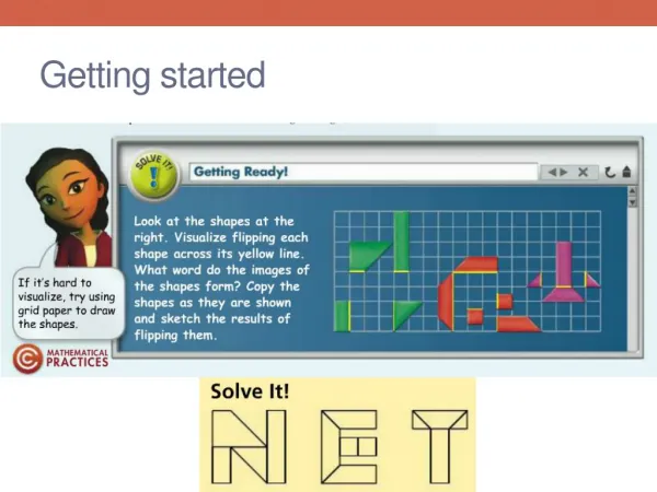
Getting Started On 144 MHZ EME Two-Way radio communication on VHF using the Moon as a reflector. Commonly know as “Moon Bounce”.
The use of the Moon as a passive communications satellite - was proposed by W.J. Bray. • It was calculated that with the available microwave transmission power of the day and low noise receivers, it would be possible to beam signals from Earth and reflect them off the Moon. • The “moon bounce” technique was developed by the United States Military in the years after World War II, with the first successful reception of echoes off the Moon being carried out at Fort Monmouth, New Jersey on January 10, 1946 by John H. DeWitt as part of Project Diana. • The “Communication Moon Relay” project that followed led to more practical uses, including a teletype link between the naval base at Pearl Harbor, Hawaii and United States Navy headquarters in Washington, DC. EME history – military purposes
50 kilowatts at 111.5 MHZ in 1⁄4-second pulses. • The first successful echo detection came on 10 January 1946 at 11:58am local time. • The Project Diana array was later used to map Venus and other nearby planets. Project Diana facts
Diana special event- n2mo https://www.youtube.com/watch?v=CdrtnFlIKRI
If two stations have adequate equipment and can simultaneously see the moon, they should be able to make a contact via EME. • Several attempts may be required to achieve success. • Signals are very weak echoes reflected from the moon’s surface. • Typically, they are usually at the noise level, or even beneath the noise, occasionally rising from the noise for brief periods In theory……..
The moon is an average of 238,855 miles away from earth. IT’s A Long Trip
Spatial Polarization Offset – “Your Horizontal Isn’t My Horizontal” Challenges - Polarization
During the lunar month, the moon travels in a slightly elliptical orbit with a distance to earth of approximately 221,500 miles at perigee (point closest to earth) and about 252,700 miles at apogee (point furthest from earth). • This distance results in about a 2.5 second delay on 2 meters, the round trip path loss is about 251.5 dB at perigee and 253.5 dB at apogee and the path loss increases with frequency. Challenges – Path loss
Joseph Hooton Taylor Jr. is an American astrophysicist and Nobel Prize in Physics laureate for his discovery with Russell Alan Hulse of a "new type of pulsar, a discovery that has opened up new possibilities for the study of gravitation. Professor joe taylor
WSJT https://physics.princeton.edu/pulsar/k1jt/
Can decode signals to <-31 dB relative to the noise floor on VHF. • CW is only copyable to about -12 dB with “Good Ears”. • The program is very stable – does not need an expensive processor to execute. • It is all open source – many developers are out there working on the product. • There are new builds and updates coming through almost monthly. • Oh Yes – IT IS FREE! Why jt65 digital for eme
The by far most used and most reliable mode of operation is JT65B, due to the readability of signals with respect to noise. • I’d would to say that 95% of all EME QSO's on 2m are performed in JT65B mode (not taking into account EME contest situations etc.). Survey says -> jt65B
http://physics.princeton.edu/pulsar/k1jt/wsjtx-doc/wsjtx-main-1.7.0.htmlhttp://physics.princeton.edu/pulsar/k1jt/wsjtx-doc/wsjtx-main-1.7.0.html
VFO Stability for digital EME is very important. What ever radio you choose, make sure it is very stable at 144 mhz. • An all mode transceiver is required – a radio that is capable of SSB / CW. • The better the filtering and stability, things will work more in your favor! Multimode transceiver
In order to participate in 2m EME communication, you absolutely need to enable your equipment to run digital modes flawlessly (no audio "hum“). • Avoid interfacing that requires you to use your microphone connector if possible! • Most radios offer a “Data Port” on the back of the radio – this is the best way to keep noise down. • Use “Snap On” chokes – take the RF of the cabling. Clean Signals are a must!
Many times during an EME session there are effects like "Faraday Rotation" which basically turns the polarization of an EME signal around by up to 90 degrees • This results in a degradation of the received signal - if the polarization cannot be switched – needless to say that under such circumstances the received EMEsignal is completely lost. • The bad news with Faraday is that this situation can last for hours! • Being able to switch the polarization of the antennas by 90 degrees is a veryefficient way to getting around this polarization change issue. • Cross Polarization Yagi’s (Horizontal/Vertical - Switchable) Faraday rotation / antennas