Next-Gen Wireless Standard: TGn.Sync Proposal
Learn about cutting-edge 802.11n standard proposal by Aon Mujtaba from Agere Systems and team for high throughput, robustness, low complexity, and global regulatory compliance.

Next-Gen Wireless Standard: TGn.Sync Proposal
E N D
Presentation Transcript
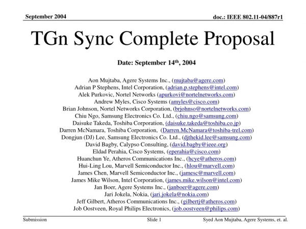
TGn Sync Proposal Date: Aug 13, 2004 Aon Mujtaba, Agere Systems Inc., (mujtaba@agere.com) Adrian P Stephens, Intel Corporation, (adrian.p.stephens@intel.com) Alek Purkovic, Nortel Networks (apurkovi@nortelnetworks.com) Andrew Myles, Cisco Systems (amyles@cisco.com) Brian Johnson, Nortel Networks Corporation, (brjohnso@nortelnetworks.com) Daisuke Takeda, Toshiba Corporation, (daisuke.takeda@toshiba.co.jp) Darren McNamara, Toshiba Corporation, (Darren.McNamara@toshiba-trel.com) Dongjun (DJ) Lee, Samsung Electronics Co. Ltd., (djthekid.lee@samsung.com) David Bagby, Calypso Consulting, (david.bagby@ieee.org) Eldad Perahia, Cisco Systems, (eperahia@cisco.com) Huanchun Ye, Atheros Communications Inc., (hcye@atheros.com) Hui-Ling Lou, Marvell Semiconductor Inc., (hlou@marvell.com) James Chen, Marvell Semiconductor Inc., (jamesc@marvell.com) James Mike Wilson, Intel Corporation, (james.mike.wilson@intel.com) Jan Boer, Agere Systems Inc., (janboer@agere.com) Jari Jokela, Nokia, (jari.jokela@nokia.com) Jeff Gilbert, Atheros Communications Inc., (gilbertj@atheros.com) Joe Pitarresi, Intel Corporation, (joe.pitarresi@intel.com) Jörg Habetha, Royal Philips Electronics, (joerg.habetha@philips.com) John Sadowsky, Intel Corporation, (john.sadowsky@intel.com) Jon Rosdahl, Samsung Electronics Co. Ltd., (jon.rosdahl@partner.samsung.com) Luke Qian, Cisco Systems, (lchia@cisco.com) Mary Cramer, Agere Systems (mecramer@agere.com) Aon Mujtaba, Agere Systems, et al
Authors (continued) Masahiro Takagi, Toshiba Corporation, (masahiro3.takagi@toshiba.co.jp) Monisha Ghosh, Royal Philips Electronics, (monisha.ghosh@philips.com) Nico van Waes, Nokia, (nico.vanwaes@nokia.com) Osama Aboul-Magd, Nortel Networks Corporation, (osama@nortelnetworks.com) Paul Feinberg, Sony Electronics Inc., (paul.feinberg@am.sony.com) Pen Li , Royal Philips Electronics (pen.li@philips.com) Peter Loc, Marvell Semiconductor Inc., (ploc@marvell.com) Pieter-Paul Giesberts, Agere Systems Inc., (pgiesberts@agere.com) Richard van Leeuwen, Agere Systems Inc., (rleeuwen@agere.com) Ronald Rietman, Royal Philips Electronics, (ronald.rietman@philips.com) Seigo Nakao, SANYO Electric Co. Ltd., (snakao@gf.hm.rd.sanyo.co.jp) Sheung Li, Atheros Communications Inc., (sheung@atheros.com) Stephen Shellhammer, Intel, (stephen.j.shellhammer@intel.com) Takushi Kunihiro, Sony Corporation, (kuni@wcs.sony.co.jp) Teik-Kheong (TK) Tan, Royal Philips Electronics, (tktan@philips.com) Tomoko Adachi, Toshiba Corporation, (tomo.adachi@toshiba.co.jp) Tomoya Yamaura, Sony Corporation, (yamaura@wcs.sony.co.jp) Tsuguhide Aoki, Toshiba Corporation, (tsuguhide.aoki@toshiba.co.jp) Won-Joon Choi, Atheros Communications Inc., (wjchoi@atheros.com) Xiaowen Wang, Agere Systems Inc., (xiaowenw@agere.com) Yasuhiko Tanabe, Toshiba Corporation, (yasuhiko.tanabe@toshiba.co.jp) Yasuhiro Tanaka, SANYO Electric Co. Ltd., (y_tanaka@gf.hm.rd.sanyo.co.jp) Yoshiharu Doi, SANYO Electric Co. Ltd., (doi@gf.hm.rd.sanyo.co.jp) Yuichi Morioka, Sony Corporation, (morioka@wcs.sony.co.jp) Youngsoo Kim, Samsung Electronics Co. Ltd., (KimYoungsoo@samsung.com) Aon Mujtaba, Agere Systems, et al
TGn Sync Proposal Team - Background • Team operated as a technical group to help motivate a rapid introduction of the 802.11n standard • Participating companies from a broad range of markets • PC • Enterprise • Consumer Electronics • Semiconductor • Handset • Public Access • Solution incorporates a worldwide perspective of perceived market demand and regulatory concerns • Team has representation from the US, Europe and the Pacific Rim Aon Mujtaba, Agere Systems, et al
Proposal Overview • High throughput and minimal design complexity • Superior robustness for a broad range of applications • Low cost, low power consumption • Scalable architecture • Seamless interoperability with 802.11 legacy devices • Flexible architecture offering regulatory compliance in all major regulatory domains while preserving interoperability Aon Mujtaba, Agere Systems, et al
PHY Summary of TGn Sync Proposal • Basic configuration delivers 243 Mbps using only two antennas • Follows historical trend of 5x for 802.11 (.11 .11b .11a/g) • Higher optional PHY data rate rates (>600 Mbps) for future generation devices • MIMO evolution of 802.11 OFDM PHY with spatial division multiplexing of spatial streams • Multiple antennas (2 mandatory, greater than 2 optional) • Preamble designed for seamless interoperability with legacy 802.11a/g • Wider bandwidth options with fully interoperable 20 MHz and 40 MHz* channel capability • Support for licensed 10 MHz modes • Optional enhancements • Advanced FEC coding techniques (RS, LDPC) • Transmit beamforming with negligible additional cost in receiving client device • 1/2 guard interval • Rate 7/8 coding *Not required in regulatory domains where prohibited. Aon Mujtaba, Agere Systems, et al
MAC Summary of TGn Sync Proposal • Supports .11e • Frame aggregation, single and multiple* destinations • Bi-directional data flow • Feedback mechanisms that enhance rate adaptation • Protection mechanisms for seamless interoperability and coexistence with legacy devices • Channel management (including receiver assisted channel training protocol) • Power management * Optional Aon Mujtaba, Agere Systems, et al
PHY Aon Mujtaba, Agere Systems, et al
Basic Tx Data Path • FEC coding • Conventional K = 7 convolutional code • Rates: 1/2, 2/3 and 3/4 • Supports legacy operation • Optional LDPC/RS • Optional rate 7/8 code • Spatial stream parsing • Frequency interleaving • Block interleaver w/ QAM bit rotation (like 11a) • 20 MHz 16 columns freq. sep. = 3 subcarriers • 40 MHz 18 columns freq. sep. = 6 subcarriers • QAM modulation • BPSK, QPSK, 16 QAM and 64 QAM • Optional 1/2 guard interval Aon Mujtaba, Agere Systems, et al
Basic Tx Data Path 2 antenna 20 MHz 2 antenna 40 MHz Aon Mujtaba, Agere Systems, et al
Basic MCS Set + Duplicate Format, BPSK R = ½ provides 6 Mbps for 40 MHz channels * Optional short GI (0.4 sec) increases rates by 11.1% for maximum data rate of 640 Mbps Aon Mujtaba, Agere Systems, et al
2x2 – 40 MHz • Only 2 RF chains => Cost effective & low power • Lower SNRs @ throughput => Low cost RF • Throughput Overhead => Robust delivery of 100 Mbps Sweet Spot for 100Mbps top-of-MAC Standard 0.8 sec GI Aon Mujtaba, Agere Systems, et al
PPDU Format Legend L- Legacy, HT- High Throughput STF = Short Training Field LTF = Long Training Field SIG = Signal Field Legacy Compatible Can be decoded by anylegacy 802.11a or g compliant device for interoperability Aon Mujtaba, Agere Systems, et al
Spoofing • RATE and LENGTH PPDU length in OFDM symbols • Spoofing • Spoofing means that the legacy RATE and LENGTH fields are falsely encoded in order to determine a specified length • L-SIG RATE = 6 Mbps spoofing duration up to ~3 msec Aon Mujtaba, Agere Systems, et al
HT-SIG Contents • MCS = Modulation Coding Scheme • Number of spatial streams • Modulation • Code rate • Length • Up to 262 kbytes • PPDU option flags • Support for advanced features • Scrambler initialization • Robust scrambler init required for packet aggregation • Strong 8-bit CRC protection Aon Mujtaba, Agere Systems, et al
HT PPDU Detection • Auto-detection scheme on HT-SIG • Q-BPSK modulation (BPSK w/ 90-deg rotation) • Pilot reversal • Combined methods provide speed and reliability Aon Mujtaba, Agere Systems, et al
Training Fields • Design priorities • Backward compatibility with 802.11a/g • Robust performance • Cost effective implementation • Low overhead These space-time diagrams apply to both 20 and 40 MHz channels Aon Mujtaba, Agere Systems, et al
Legacy Compatible Preamble CDD The L-STF, L-LTF, L-SIG and HT-SIG are transmitted as a single spatial stream. This may be either transmitted on all Tx antennas via a method such as Cyclic Delay Diversity (CDD), or on a single antenna. These are implementation options. Requirement: These fields must be transmitted in an omni-directional mode that can be demodulated by legacy receivers. or single antenna Aon Mujtaba, Agere Systems, et al
HT Training Fields • HT-STF • Used for 2nd AGC • HT-LTF • Used for MIMO channel estimation • Additional frequency or time alignment • Tone interleaving of spatial streams Aon Mujtaba, Agere Systems, et al
HT Short Training Field • 24 tones – interleaved across spatial streams • Excellent space-frequency observability • 1.6 sec period • 2nd AGC • Reduces ADC requirement by 1 bit • Significant cost & power reduction • Eliminates MIMO AGC mismatch • Robust packets for aggregation Aon Mujtaba, Agere Systems, et al
HT Long Training Fields Aon Mujtaba, Agere Systems, et al
Spatial Stream Tone Interleaving • Color indicate spatial stream • Each HT-LTF has equal representation from all spatial streams • Eliminates avg. power fluctuation across LTFs • HT-LTS symbols are selected to control PAPR • Distinct symbol designs for different number of spatial streams Aon Mujtaba, Agere Systems, et al
Why Tone Interleaving on HT-LTF? No toneinterleaving Clipping in Rx ADC? Even if all spatial streams are transmitted with equal power, they can create power differences at the receiver. For Model B (15 n sec delay spread) this can result in frequent power differentials of ~6dB between spatial streams. Tone interleaving of spatial streams results in averaging power levels across all spatial streams on each training symbol. The result is essentially no Rx power fluctuation of the STS and LTS with respect to the data symbols. Aon Mujtaba, Agere Systems, et al
40 MHz Channel • 108 data + 6 pilot subcarriers • Duplicate format on legacy part • Provides interoperability between 20 MHz and 40 MHz transmissions Aon Mujtaba, Agere Systems, et al
40 MHz PPDU Format • Duplicate format preamble • Provides interoperability with 20 MHz legacy STAs • Data, pilot and training tones in each 20 MHz subchannel are identical to corresponding 20 MHz format • 90 deg phase shift on upper sub-channel controls PAPR • HT part • 108 data tones + 6 pilots • 3 center nulls (not shown) Aon Mujtaba, Agere Systems, et al
Duplicate Receiver Combining Equalizer: Simple MRC combining Note: If upper sub-channel is not present, combining weights are zero Aon Mujtaba, Agere Systems, et al
40/20 MHz Interoperability • 20 MHz PPDU 40 MHz receiver • Combine modulation symbols from upper & lower sub-channels • 20 MHz PPDU in lower sub-channel • Zero combining weights in upper subchannel • No loss in performance relative to a 20 MHz receiver • Use differential sub-channel energy to detect 20 vs. 40 MHz signals • 40 MHz PPDU 20 MHz receiver • One sub-channel is sufficient to decode the L-SIG • Detects only half of the 40 MHz signal 3 dB performance penalty for 20 MHz clients • See MAC slides for additional information on 40/20 inter-op Aon Mujtaba, Agere Systems, et al
Transmit Beamforming • Basic Beamforming • Cost, complexity, and power consumption contained in the AP • Enterprise AP, media server AP, set-top box, or desktop PC • Very low overhead for BF receive only client • Low client cost, essentially zero overhead • Low power consumption – battery operated • Basic MCS set • Channel sounding PPDU provides capability to estimate the channel from all Tx antennas • Receiver does not need to know the beamforming specifics at the transmitter • Simple packet exchange for calibration • Optional Advanced Beamforming (ABF) • Extended MCS Set • Provides independent modulation/coding across spatial streams • Support for unequal spatial stream power loading • Support for bi-directional beamforming Aon Mujtaba, Agere Systems, et al
4 Tx AP => 2 Rx Client ~10 dB gain over Basic 2x2! => cost effective server-client Aon Mujtaba, Agere Systems, et al
Optional Advanced Coding Modes • Low Density Parity Check (LDPC) • Superior performance at high code rates (7/8) • Reed-Solomon (RS) • Outer code concatenated with inner convolutional code • Very low cost, mature technology Aon Mujtaba, Agere Systems, et al
LDPC yields a 2x2 20 MHz high throughput solution at reasonable SNR! Aon Mujtaba, Agere Systems, et al
MAC Aon Mujtaba, Agere Systems, et al
MAC Challenges in HT Environment • HT requires an improvement in MAC Efficiency • HT requires effective Rate Adaptation • HT requires Legacy Protection Aon Mujtaba, Agere Systems, et al
New MAC Features • Aggregation Format • Aggregation Exchanges • Protocol for training • Protocol for reverse direction data • Single and multiple responder • Header Compression • Protection Mechanisms • Coexistence & Channel Management • MIMO Power Management Aon Mujtaba, Agere Systems, et al
Robust Structure Aggregation Framing is a purely-MAC function (PHY has no knowledge of MPDU boundaries) Aggregation Framing Aon Mujtaba, Agere Systems, et al
MAC Header Compression • MHDR MPDU carries repeated Header fields • CHDATA MPDU refers to previous MHDR MPDU • HID field ties the two together • Context only within current aggregate Aon Mujtaba, Agere Systems, et al
Aggregate Exchange Sequences • MPDU or frame exchange sequences now extended to aggregate exchange sequences in which groups of frames are exchanged “at a time” • Allows effective use of Aggregate Feature • Allows control, data and acknowledgement to be sent in the same PPDU • An initiator sends a PPDU and a responder may transmit a response PPDU • Either PPDU can be an aggregate (“Initiator” / “responder” are new terms relating to roles in aggregate exchange protocol) Aon Mujtaba, Agere Systems, et al
Basic Aggregate Exchange Aon Mujtaba, Agere Systems, et al
Reverse Direction Data Flow • Gives an opportunity for a responder to transmit data to an initiator during the initiator’s TXOP • Aggregates data with response control MPDUs • Reduces Contention • Effective in increasing TCP/IP performance Aon Mujtaba, Agere Systems, et al
Reverse Direction Protocol Aon Mujtaba, Agere Systems, et al
Training Protocol • Support for PHY closed-loop modes with on-the-air signalling • Request for training and feedback are carried in control frames • Rate feedback supported • Transmit beamforming training supported • sounding packet • calibration exchange • Timing of response is not constrained permitting a wide range of implementation options Aon Mujtaba, Agere Systems, et al
Training Protocol Aon Mujtaba, Agere Systems, et al
Multiple Receiver Aggregation • Aggregates can contain MPDUs addressed for multiple receiver addresses (MRA) • MRA may be followed by multiple responses from the multiple receivers • MRA is effective in improving throughput in applications where frames are buffered to many receiver addresses Aon Mujtaba, Agere Systems, et al
Periodic Multi-Receiver Aggregation Aon Mujtaba, Agere Systems, et al
MRA contains multiple IAC for One per response At most one per receiver IAC specifies response offset and duration Multiple Responses Aon Mujtaba, Agere Systems, et al
Protection Mechanisms • LongNAV • An entire sequence is protected by NAV set using MPDU duration field or during contention-free period • CF-end packet at end of EDCA TXOP sequence may be used to return unused time by resetting NAV • Pairwise Spoofing • Protection of pairs of PPDUs sent between an initiator and a single responder • Uses Legacy PLCP header duration spoofing • Single-ended Spoofing • Protection of aggregate and any responses using legacy PLCP spoofing at the initiator only • Can be used to protect multiple responses Aon Mujtaba, Agere Systems, et al
LongNAV protection • Provides protection of a sequence of multiple PPDUs • Provides a solution for .11b • Comes “for free” with polled TXOP • Gives maximum freedom in use of TXOP by initiator Aon Mujtaba, Agere Systems, et al
Protects pairs of PPDUs (current and following) Very low overhead, suitable for short exchanges Places Legacy devices into receiving mode for spoofed duration Spoofing is interpreted by HT devices as a NAV setting Pairwise Spoofing Protection Aon Mujtaba, Agere Systems, et al
Protects MRA and all responses Very low overhead, suitable for short exchanges Places legacy devices into receiving mode for spoofed duration Same level of protection as initiator CTS-to-Self Assuming CTS is sent at the lowest rate Single-Ended Spoofing Protection Aon Mujtaba, Agere Systems, et al
Following Packet Descriptor (FPD) Protocol Aon Mujtaba, Agere Systems, et al
Operating Mode Selection • BSS operating mode controls the use of protection mechanisms and 40/20 width switching by HT STA • Supports mixed BSS of legacy + HT devices • HT AP-managed modes • If only the control channel is overlapped, managed mixed mode provides a low overhead alternative to mixed mode • If both channels are overlapped, 20 MHz base mode allows an HT AP to dynamically switch channel width for 40 MHz-capable HT STA Aon Mujtaba, Agere Systems, et al