
The Transistor as a Switch
E N D
Presentation Transcript
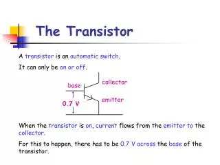
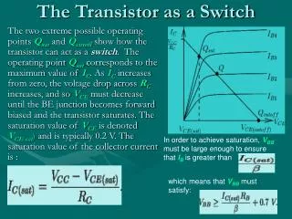
The Transistor as a Switch The two extreme possible operating points Qsat and Qcutoff show how the transistor can act as a switch. The operating point Qsat corresponds to the maximum value of IC. As IC increases from zero, the voltage drop across RC increases, and so VCE must decrease until the BE junction becomes forward biased and the transistor saturates. The saturation value of VCE is denoted VCE(sat) and is typically 0.2 V. The saturation value of the collector current is : In order to achieve saturation, VBBmust be large enough to ensure that IBis greater than which means that VBB must satisfy:
The Transistor as a Switch • In saturation mode, the transistor is on, allowing maximum current to flow. • At the other extreme, Qcutoff the transistor is cutoff. • This requires IB=0, and hence IC=0. The cutoff value of VCE is : VCE(cutoff) = VCC • Of course, in this mode the transistor is off. With the simple model this requires .
The Transistor as an Amplifier AC Model and Parameters We will also need an AC model for the transistor. There are AC parameters and , which are in general slightly different from their DC counterparts. However, we will assume them to be the same in this course. The equations for the AC currents are and Of course we also have ie = ib + ic . The AC equivalent circuit could be drawn as shown here; where I
The Transistor as an Amplifier When the DC operating point Q is in the active region, the transistor can act as an amplifier to AC signals. For such purpose, Q should be set midway between Qsat and Qcutoff to allow for the maximum possible voltage excursions.
Small Signal Amplifier The two transistor types have opposite polarity power supplies. The polarity of the capacitors is reversed. If the transistors have the same characteristics, then resistor values are the same in both circuits. • R1 and R2 are the base bias resistors, setting the bias point. • R3 is the collector load resistor. • R4 is the emitter stabilizing resistor. • C3 is the emitter decoupling capacitor. • C1 and C2 are coupling capacitors which allow ac signals to pass but block dc