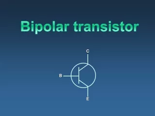
TRANSISTOR
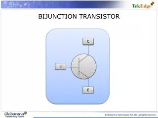
TRANSISTOR. BJT : DC BIASING. Transistor Currents. …( Eq. 3.1). Emitter current (I E ) is the sum of the collector current (I C ) and the base current (I B ) . Kirchhoff’s current law;. Collector Current (I C ). …( Eq. 3.2). Collector current (I C ) comprises two components ;


TRANSISTOR
E N D
Presentation Transcript
TRANSISTOR BJT : DC BIASING
Transistor Currents …(Eq. 3.1) Emitter current (IE) is the sum of the collector current (IC) and the base current (IB) . Kirchhoff’s current law;
Collector Current (IC) …(Eq. 3.2) • Collector current (IC) comprises two components; • majority carriers (electrons) from the emitter • minority carriers (holes) from reverse-biased BC junction → leakage current, ICBO • Total collector current (IC); • Since leakage current ICBO is usually so small that it can be ignored.
Collector Current (IC) …(Eq. 3.3) Then; The ratio of IC to IE is called alpha (α), values typically range from 0.95 to 0.99.
Base Current (IB) …(Eq. 3.4) IB is very small compared to IC; The ratio of IC to IB is the dc current gain of a transistor, called beta (β) The level of beta typically ranges from about 50 to over 400
Current & Voltage Analysis IB: dc base current IE: dc emitter current IC: dc collector current VBE: dc voltage across base-emitter junction VCB: dc voltage across collector-base junction VCE: dc voltage from collector to emitter Transistor bias circuit. Consider below figure. Three dc currents and three dc voltages can be identified
Current & Voltage Analysis …(Eq. 3.5) …(Eq. 3.6) When the BE junction is forward-biased, it is like a forward-biased diode. Thus; (Si = 0.7, Ge = 0.3) From HVK, the voltage across RB is By Ohm’s law; Solving for IB
Current & Voltage Analysis …(Eq. 3.7) …(Eq. 3.8) The voltage at the collector is; The voltage drop across RC is VCE can be rewritten as The voltage across the reverse-biased CB junction is
Transistor as Amplifier Transistor is capable to amplify AC signal : (output signal > input signal) Eg: Audio amplifier that amplify the sound of a radio
Transistor Amplifier Circuit Analysis • There are 2 analysis; • DC Analysis • AC Analysis • Transistor will operate when DC voltage source is applied to the amplifier circuit • Q-point must be determined so that the transistor will operate in active region (can operate as an amplifier)
Transistor Amplifier Circuit Analysis Q-Point • Q-Point • Operating point of an amplifier to state the values of collector current (ICQ) and collector-emitter voltage (VCEQ). • Determined by using transistor output characteristic and DC load line
DC LOAD LINE Saturation Region Q-Point DC Load Line Cutoff Region • DC Load Line • A straight line intersecting the vertical axis at approximately IC(sat) and the horizontal axis at VCE(off). • IC(sat) occurs when transistor operating in saturation region • VCE(off) occurs when transistor operating in cut-off region
DC LOAD LINE (Example) VCC = 8V Draw DC Load Line and Find Q-point. Answers; RC = 2 kΩ RB = 360 kΩ
DC LOAD LINE (Example) Draw DC Load Line and Find Q-point. Answers; • Q-point can be obtained by calculate the half values of maximum IC and VCE 2 mA 4V
DC Analysis of Amplifier Circuit Amplifier Circuit Amplifier Circuit w/o capacitor
DC Analysis of Amplifier Circuit Amplifier Circuit w/o capacitor • Refer to the figure, for DC analysis: • Replace capacitor with an open-circuit • R1 and R2 create a voltage-divider circuit that connect to the base • Therefore, from DC analysis, you can find: • IC • VCE
DC Analysis of Amplifier Circuit Thevenin Theorem; Amplifier Circuit w/o capacitor Simplified Circuit
DC Analysis of Amplifier Circuit From Thevenin Theorem; 2 1 From HVK; 1 2 Important equation for DC Analysis
TRANSISTOR BJT BIASING CIRCUIT
BJT BIASING CIRCUIT Fixed Base Bias Circuit (Litar Pincangan Tetap) Fixed Bias with Emitter Resistor Circuit (Litar Pincangan Pemancar Terstabil) Voltage-Divider Bias Circuit (Litar Pincangan Pembahagi Voltan) Feedback Bias Circuit (Litar Pincangan Suap-Balik Voltan)
FIXED BASE BIAS CIRCUIT • This is common emitter (CE) configuration • Solve the circuit using HVK • 1st step: Locate capacitors and replace them with an open circuit • 2nd step: Locate 2 main loops which; • BE loop • CE loop
FIXED BASE BIAS CIRCUIT 1st step: Locate capacitors and replace them with an open circuit
FIXED BASE BIAS CIRCUIT BE Loop CE Loop 1 1 2 2 2nd step: Locate 2 main loops.
FIXED BASE BIAS CIRCUIT • From HVK; IB 1 A BE Loop Analysis
FIXED BASE BIAS CIRCUIT • From HVK; • As we known; • Subtituting with IC A B B 2 CE Loop Analysis
FIXED BASE BIAS CIRCUIT • DISADVANTAGE • Unstable – because it is too dependent on β and produce width change of Q-point • For improved bias stability , add emitter resistor to dc bias.
FIXED BASE BIAS CIRCUIT • Find IC, IB, VCE, VB, VC, VBC? (Silikon transistor); • Answers; • IC = 2.35 mA • IB = 47.08 μA • VCE = 6.83V • VB = 0.7V • VC = 6.83V • VBC = -6.13V Example 1
FIXED BIAS WITH EMITTER RESISTOR Resistor, RE added • An emitter resistor, RE is added to improve stability • Solve the circuit using HVK • 1st step: Locate capacitors and replace them with an open circuit • 2nd step: Locate 2 main loops which; • BE loop • CE loop
FIXED BIAS WITH EMITTER RESISTOR 1st step: Locate capacitors and replace them with an open circuit
FIXED BIAS WITH EMITTER RESISTOR CE Loop BE Loop 1 1 2 2 2nd step: Locate 2 main loops.
FIXED BIAS WITH EMITTER RESISTOR • From HVK; • Recall; • Subtitute for IE 1 BE Loop Analysis
FIXED BIAS WITH EMITTER RESISTOR • From HVK; • Assume; • Therefore; 2 CE Loop Analysis
FIXED BIAS WITH EMITTER RESISTOR • Find IC, IB, VCE, VB, VC, VE & VBC? (Silikon transistor); • Answers; • IC = 2.01 mA • IB = 40.1 μA • VCE = 13.97V • VB = 2.71V • VE = 2.01V • VC = 15.98V • VBC = -13.27V Example 2
VOLTAGE DIVIDER BIAS CIRCUIT • Provides good Q-point stability with a single polarity supply voltage • Solve the circuit using HVK • 1st step: Locate capacitors and replace them with an open circuit • 2nd step: Simplified circuit using Thevenin Theorem • 3rd step: Locate 2 main loops which; • BE loop • CE loop
VOLTAGE DIVIDER BIAS CIRCUIT 1st step: Locate capacitors and replace them with an open circuit
VOLTAGE DIVIDER BIAS CIRCUIT • 2nd step: : Simplified circuit using Thevenin Theorem From Thevenin Theorem; Thevenin Theorem; Simplified Circuit
VOLTAGE DIVIDER BIAS CIRCUIT CE Loop BE Loop 1 1 2 2 2nd step: Locate 2 main loops.
VOLTAGE DIVIDER BIAS CIRCUIT • From HVK; • Recall; • Subtitute for IE 1 BE Loop Analysis
VOLTAGE DIVIDER BIAS CIRCUIT • From HVK; • Assume; • Therefore; 2 CE Loop Analysis
VOLTAGE DIVIDER BIAS CIRCUIT • Find RTH, VTH, IC, IB, VCE, VB, VC, VE & VBC? (Silikon transistor); • Answers; • RTH = 3.55 kΩ • VTH = 2V • IC = 0.85 mA • IB = 6.05 μA • VCE = 12.22V • VB = 1.978V • VE = 1.275V • VC = 13.5V • VBC = -11.522V Example 3