Overview and Test Results of the DOR-DOM Communication System
This document provides a comprehensive overview of the DOR-DOM communication system, including the OSI model's application within the system, block diagrams, packet presentations, and detailed encoding/decoding mechanisms. It covers critical functionality tests such as power-on synchronization, data polling, framing, deframing, and DOM reboot handling. Key issues related to noise, data security, and communication thresholds are addressed, along with next steps for further improvements and testing, such as the implementation of the SYSRES command and time calibration.

Overview and Test Results of the DOR-DOM Communication System
E N D
Presentation Transcript
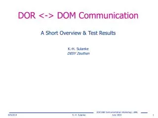
DOR <-> DOM Communication A Short Overview & Test Results K.-H. Sulanke DESY Zeuthen K.-H. Sulanke
Contents • OSI Model • DOR Block Diagram • Packet Presentation • Control and Data Bytes • Bit Encoding / Decoding • Status • Next Steps K.-H. Sulanke
OSI (Open System Interconnect) 7-Layer Model • Layer 2 by DOR firmware • Physical Layer: • 140 Ω twisted pair cable • DSUB-9 connector • … • Data Link: • UART like protocol • Half Duplex • Master / Slave • … K.-H. Sulanke
Data Buffer SRAM 2 x 256Kx16 P C I - C o r e DOM 1..4 PCI Bus Altera FPGAEP20K200E DOM 5..8 Config JTAG JTAG JTAG Altera PLD EPM7064 FLASH 1M x 8 Clock 96 V Cable Interface #3 Cable Interface #2 Cable Interface #1 Cable Interface #4 DOR, Block Diagram 2 2 2 2 Reload K.-H. Sulanke
FPGA +96V 10 ADC 10 Bit PREAMP -96V Cable Con. 8 DAC 8 Bit RS485 alternative use Cable Interface Scheme K.-H. Sulanke
Rx / Tx Data Path, one Wire Pair PCI Bus FPGA Comm. DAC Framing, Encoding Tx_FIFO_A,B 32 8 8 Data_in Data_out Cable Con. Empty AlmEmpty ReadEna WriteEna Address Decoder 2 Wire Pair Control (8) State Machines 4 BusCycle 2 Message_rcvd InterruptControl 1 Interrupt Comm. ADC Diff. Rec. DeFrame, Decoding Rx_FIFO_A,B 10 8 Data_out Data_in AlmFull Empty WriteEna ReadEna Internal FIFOs will be replaced by external SRAM K.-H. Sulanke
31 24 23 16 15 0 User_Defined Packet_Type Packet_Length Packet Header Packet_Length: 0…65535, amount of bytes to be transferred Packet_Type: User_Defined: not relevant for hardware K.-H. Sulanke
Packet Presentation Example: Sending 7 bytes to DOM_B 32 bit Tx Buffer Cable incremental number to detect lost packets Green = Control bytes added by firmware K.-H. Sulanke
Byte Encoding Data Byte Control Byte Odd Parity of Adr0..1, Cmd0..3 K.-H. Sulanke
Commands K.-H. Sulanke
Command Sequence K.-H. Sulanke
DOM Reboot Problem • After DOM power on the DOM is rebooting two times • Every reboot means a FPGA-reload as well • Problem: asynchronous loss of communication • Solution: synchronization with the data polling, DOM may only reboot after answering on DRREQ with DRBT • DOR stops all data transfer and sends COMRES until it gets an IDLE back K.-H. Sulanke
Tested Functionality • Power On synchronization (COMRES command) • DOM A/B data polling (DRREQ, DRAND) • Framing and Deframing (STF, EOF) • Prevention of DOM buffer overrun (BFSTAT, MRNB, MRWB) • DOM Reboot handling (DRBT command) • Automatically detection of a missing DOM -> full bandwidth dedicated to the other one • SYSRES and TCAL not yet tested K.-H. Sulanke
Data Encoding • DC-free bit encoding, 1MBit/s • “0” = quiet line, “1” = bipolar rectangular pulse, T=1µs Tx (DAC) and Rx Signal using the new Ericsson Cable (3.4 km) 1001111011…. HL_edge > 30 mV Measured between GND and one transformer tap using a Tektronix standard probe K.-H. Sulanke
Start Stop 01001110 72hex Start point dU Stop point dt Digital Decoding • evaluating the HL-edge in a time window to detect a “1” • baseline correction not necessary K.-H. Sulanke
Noise • problem: missing of a “standard” noise source • noise by neon lamp starters and electrical engines used to evaluate the design progress noise caused by a neon table lamp, measured at the preamp’s out K.-H. Sulanke
Digital Filtering • simple digital mean value calculation over 4 ADC samples (bit time is 20 samples) mean(adc[9..0])i=(adc[9..2]i-1 + adc[9..2]i-2 + adc[9..2]i-3+ adc[9..2]i-4) lower two bits not used, 0..3 -> 0..3mV • goal is to eliminate high frequency noise spikes • the filter algorithm is limited by the available FPGA resources • Test using “natural” noise sources have shown a significant improvement • more data security by decoding the stop bit • only if the stop bit has arrived the byte is written to the Rx FIFO • prevents zero bytes, caused by single noise spike-“start bits” K.-H. Sulanke
Status • long term DOS-test with 4 DOMs (2 days, 3.4km new Ericsson cable, 48KB/s/DOM) error free under lab conditions • DOM-Reboot needs still some debugging • DOM Soft Boot (command SYSRES) still has to be tested • Time calibration (command TCAL) not yet implemented K.-H. Sulanke
Next Steps • DOM Soft Boot (command SYSRES) and TCAL test • Debug FIFO to record the last 256 control bytes • Possible improvements: • Adaptive edge decoder, especially for the DOM side (pk-pk value changes from 60mV to 1.2V, when a DOM is responding, but the other one is receiving) • Automatic adaption of the communication threshold after DOM power on • 8b/10b encoding scheme for better signal/noise ratio and/or higher data rates • 32 bit checksum implementation • Hardware initiated retransmit in case of an error K.-H. Sulanke