Download
1 / 43
430 likes | 644 Vues
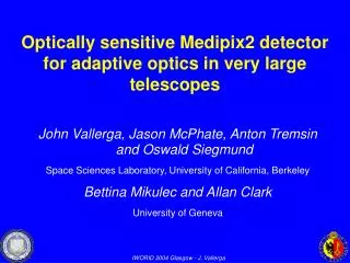
Optically sensitive Medipix2 detector for adaptive optics in very large telescopes. John Vallerga, Jason McPhate, Anton Tremsin and Oswald Siegmund Space Sciences Laboratory, University of California, Berkeley Bettina Mikulec and Allan Clark University of Geneva. Adaptive optics tutorial*.

E N D
Optically sensitive Medipix2 detector for adaptive optics in very large telescopes John Vallerga, Jason McPhate, Anton Tremsin and Oswald Siegmund Space Sciences Laboratory, University of California, Berkeley Bettina Mikulec and Allan Clark University of Geneva
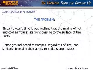
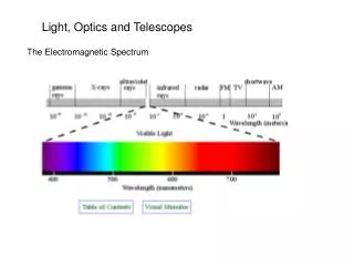
Adaptive optics tutorial* Turbulence in earth’s atmosphere makes stars twinkle More importantly, turbulence spreads out light; makes it a blob rather than a point *Adapted from AO lectures of Claire Max, Astro 289C, UC Santa Cruz Even the largest ground-based astronomical telescopes have no better resolution than a 20 cm telescope!
blur Optical consequences of turbulence • Temperature fluctuations in small patches of air cause changes in index of refraction (like many little lenses) • Light rays are refracted many times (by small amounts) • When they reach telescope they are no longer parallel • Hence rays can’t be focused to a point: Point focus Parallel light rays Light rays affected by turbulence
How a deformable mirror works (idealization) BEFORE AFTER Incoming Wave with Aberration Deformable Mirror Corrected Wavefront
Adaptive optics increases peak intensity of a point source Lick Observatory No AO With AO Intensity With AO No AO
Optical Medipix tube goes here Schematic of adaptive optics system Feedback loop: next cycle corrects the (small) errors of the last cycle
Lick adaptive optics system at 3m Shane Telescope DM Wavefront sensor Off-axis parabola mirror IRCAL infra-red camera
How to measure turbulent distortions (one method among many) “Shack-Hartman” WFS
ESO VLT Gemini South The new generation: adaptive optics on 8-10 m telescopes Summit of Mauna Kea volcano in Hawaii: Subaru 2 Kecks Gemini North And at other places: MMT, VLT, LBT, Gemini South
Neptune in infra-red light (1.65 microns) With Keck adaptive optics Without adaptive optics 2.3 arc sec May 24, 1999 June 27, 1999
VLT NAOS AO first light Cluster NGC 3603: IR AO on 8m ground-based telescope achieves same resolution as HST at 1/3 the wavelength Hubble Space Telescope WFPC2, = 800 nm NAOS AO on VLT = 2.3 microns
Faint companions around bright stars Two images from Palomar of a brown dwarf companion to GL 105 End Tutorial Credit: David Golimowski
Vision Science End Tutorial
Next generation of large telescopes (proposed) 30 m diameter: • California Extremely Large Telescope (CELT) - • Thirty Meter Telescope (TMT) 50 m diameter: • EURO50 on La Palma 100 m diameter: • European Southern Observatory’s “OverWhelmingly Large Telescope” (OWL) All propose AO systems with > 5000 actuators
WFS detector requirements • High optical QE for dimmer guide stars • Lots of pixels - eventually 512 x 512 • Very low readout noise • kHz frame rates The last three are not simultaneously achievable with the current generation of CCDs
MCP Detectors at SSL Berkeley COS FUV for Hubble (200 x 10 mm windowless) 25 mm Optical Tube GALEX 68 mm NUV Tube (in orbit)
Photocathode converts photon to electron MCP(s) amplify electron by 104 to 108 Rear field accelerates electrons to anode Patterned anode measures charge centroid Imaging, Photon Counting Detectors
GaAs Photocathodes (GenIII) Photocathode type determines wavelength response • Soft x-ray to near IR
Wavefront Sensor Event Rates(example for big telescope) • 5000 centroids • Kilohertz feedback rates (atmospheric timescale) • 1000 detected events per spot for sub-pixel centroiding • 5000 x 1000 x 1000 = 5 Gigahertz counting rate! • Requires integrating detector
Our concept • An optical imaging tube using: • GaAs photocathode • Microchannel plate to amplify a single photoelectron by 104 • Bare Medipix2 to count these events per pixel
First test detector • Demountable detector • Simple lab vacuum, no photocathode • Windowless – UV sensitive
Initial Results It Works! Lower gain, higher rear field First light!
Spatial Resolution Group 3-2 visible 9 lp/mm = 55µm (Nyquist limit) 100 µs 1 s
Interesting tangent - sub pixel resolution Use single spot events and calculate centroids Accumulate event x,y list 2-d histogram on finer pitch 9 lp/mm
Interesting tangent - sub pixel resolution Calculate centroids of each event Accumulate event x,y list 2-d histogram on finer pitch 16 lp/mm
Flat Field MCP deadspots Hexagonal multifiber boundaries 1200 cts/bin - 500Mcps
Flat Field (cont) Histogram of Ratio consistent with counting statistics (2% rms) Ratio Flat1/Flat2
Future Work (3 yr. NOAO grant) • Optimize MCP-Medipix2 interface design • Design and build tube with Medipix2 and GaAs • Develop parallel readout with European collaborators • Develop FPGA to reduce output bandwidth • 5 million centroids/s vs. 262 million pixels/s. • Test at AO laboratory at CFAO, U.C. Santa Cruz • Test at telescope
Univ. of Barcelona University of Cagliari CEA CERN University of Freiburg University of Glasgow Czech Academy of Sciences Mid-Sweden University University of Napoli NIKHEF University of Pisa University of Auvergne Medical Research Council Czech Technical University ESRF University of Erlangen-Nurnberg Acknowledgements This work was funded by an AODP grant managed by NOAO and funded by NSF Thanks to the Medipix Collaboration:
h Isoplanatic Angle (0) & Sky Coverage Bright stars + 0 =1% sky coverage Telescope Primary mirror
Can achieve>70% skycoverage withlaserguidestaradaptive optics!
589.2 nm L d Laser Guide Star Parallax • “Star” more of a streak • Shape changes over pupil • Can use pulsed laser to limit spatial extent • Requires gated detector
Deformable mirrors come in many sizes • Range from 13 to > 900 actuators (degrees of freedom) ~ 300mm ~ 50 mm Xinetics