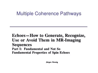
Multiple Coherence Pathways
Multiple Coherence Pathways. T E. T E. Simple spin echo. spin echo. 90 y. 180 x. d. a. b. c. stimulated echo. Hahn echo. 90 y. 90 x. 90 x. d. e. a. b. c. f. T M. T E. T E. T E. Hahn (90-90) and stimulated (90-90-90) echoes. Hennig Fig. 2. Repeated flip =90 o.

Multiple Coherence Pathways
E N D
Presentation Transcript
TE TE Simple spin echo spin echo 90y 180x d a b c
stimulated echo Hahn echo 90y 90x 90x d e a b c f TM TE TE TE Hahn (90-90) and stimulated (90-90-90) echoes Hennig Fig. 2
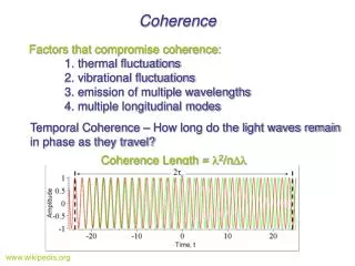
What is an echo? • Signal peak (in time) cause by net alignment of magnetization • Spin echoes: perfect alignment of isochromats • Any distribution of isochromats is refocused • More generally: perfect alignment is not required to have a peak in signal • Hahn, stimulated echoes to not have isochromats aligned • Magnetization is “bunched up” on one side of xy plane • Many echoes require distribution is isochromats • Unlike NMR, heavy dephasing (distribution) is the norm in MRI • MRI insufficient inhomogeneity to maintain long-term coherence • Instead, use gradients to reliably dephase (spoil) and rely on short-term coherences • Can we find a representation that is better than isochromat vectors?
Shortcomings of vector representation Vector representation (e.g., Bloch): [Mx My Mz] Problems: • Evolution of magnetization (in absence of RF) has 2 independent components (transverse & longitudinal), but vectors have 3 • Fundamentally treats single isochromats, where MRI essentially always encounter distributions This is why echo evolution is so complicated to depict using vectors (both temporally and spatially) Phasegraph representation addresses both of these issues
Alternate representation of magnetization Problem 1: Evolution of magnetization has 2 independent components (transverse & longitudinal), but vectors have 3 Replace: [Mx My Mz] With: [F=Mx+iMy Mz] In absence of RF, F and Mz evolve independently relaxation, precession represented by scalar multiples no need to worry about coupling between Mx, My
0o 180o 90o Single RF pulse acts like 3 separate pulses Alternate representation of magnetization Problem 1: Evolution of magnetization has 2 independent components (transverse & longitudinal), but vectors have 3 Replace: [Mx My Mz] With: [F=Mx+iMy Mz] Effect of RF pulse: F+ = F cos2(/2) + F* sin2(/2) - i Mz sin() Mz+ = Mzcos2(/2) - Mzsin2(/2) - i (F-F*)sin()
Fractional components in arbitrary RF pulse fraction flip angle (degrees)
Configuration theory (coherence pathways) Problem 2: Vectors fundamentally represent single isochromats, where MRI essentially always encounter distributions Mz Mx Hennig, Fig 4 Mz Mx Hennig, Eqs 8-11 * typos in Hennig?
Configuration theory (coherence pathways) What do Fn, Fn*, Zn represent? This is just a useful decomposition of the magnetization (e.g., like Fourier decomposition of an image/object) Decomposition coefficient = how much magnetization expresses this structure Hennig calls “configurations” (others call “coherences”) Each configuration is a potential echo (allow it to rephase, signal is proportional to its coefficient) No mystical properties (e.g., quantum mechanics not needed)! Hennig, Fig 4
Fn+ = Fn-1 cos2(/2) + Fn* sin2(/2) + Zn sin() (Fn*)+ = Fn+1* cos2(/2) + Fn-1* sin2(/2) + Zn*sin() Zn+ = Zn cos() + (Fn* - Fn)sin() (see Eq 13-15) Track flow of magnetization between configurations phase evolution exchange between configurations Echo formation time RF pulses
Time evolution of signal dynamics Differs from previous via starting conditions (i.e., preparatory pulses)
Time evolution of signal dynamics Differs from first via flip angle