Download
1 / 15
150 likes | 269 Vues
5. Electron Emission From Metallic Surfaces. 전기공학과 이 승 수. 5.1 Introduction.

E N D
5. Electron Emission From Metallic Surfaces 전기공학과 이 승 수
5.1 Introduction The purpose of this chapter is to discuss very briefly the mechanisms giving rise to, and the characteristics of, electron emission from metallic surfaces. Should more detailed information be required reference should be made to other articles in which these phenomena are dealt with most comprehensively. The emission from electrodes situated in a high vacuum only is considered because this means that one is then really only concerned with the basic emission processes themselves without having to take into account the added complexity of any addition phenomena that would occur in say a gaseous or a liquid dielectric between the electrodes.
5.2 Classical mechanisms of electron emission from metallic surface The electrons are represented as being imprisoned in a potential well of depth x. the bottom of the well corresponds to the potential energy of an electron at rest inside the metal. The depth x therefore corresponds to the energy required to being an electron from its rest condition inside the metal into the condition where it is at rest outside the metal and a large distance from the metal surface. Inside the metal the electrons are moving and have kinetic energies distributed between a series of discrete, although finely separated, energy levels. These energy levels are all lower than that of an electron rest in the vacuum outside the metal. The highest energy level occupied by the electrons is known as the Fermi level and in Fig. 5.1 the value of this energy level is . The difference (x- ) is referred to as the work function ( ) of the metal since this is the work necessary to remove an electron from the metal by giving it enough energy to overcome the potential barrier.
5.2 Classical mechanisms of electron emission from metallic surface The force on an electron having a charge –q, is , where x is the distance from the metal surface, and the energy of the electron at x is . The electric field E at the surface of the metal is constant and it provides a contribution –qEx to the potential energy of the electron. Therefore the potential energy P as a function of the distance x from the metal-vacuum interface is (1) Equation (1) shows that the presence of an electric field reduces the height of the potential barrier and that the maximum height of the potential barrier is now and this occurs when
5.2 Classical mechanisms of electron emission from metallic surface • In the case of metals having no electric field at their surface the electron must be supplied with sufficient kinetic energy by other means to enable it to surmount the potential barrier. In this case the energy can be supplied by heating the metal (thermionic emission) or by the impact of light quanta of sufficient energy (photo-electric emission) • For electrically stressed metals the potential barrier is reduced in height by the application of the electric field and (1) sufficient energy must then be given to the electron, by heating the metal for it to overcome the reduced barrier (Shottky emission) or (2) the barrier must be made thinner by the application of an even stronger electric field at the metal surface, so that the electron can now penetrate the barrier by virtue of its wave-like characteristics (field or cold emission).
5.2 Classical mechanisms of electron emission from metallic surface 5.2.1 Thermionic emission Where J is the current density, K1 is the thermionic emission constant, T is the absolute temperature, work function , k Boltzmann’s constant and S the emitting area. This relationship is only applicable to emission from devices at high temperatures, such as filaments in electronic tubes, and the emission predicted by it at moderate temperatures is negligible. 5.2.2 Schottky emission Schottky postulated that under the action of high electric fields the work function of the metal is lowered by an amount q3/2E1/2 so that the potential barrier takes the form shown in Fig 5.2, where . The magnitude of the electron emission, under the combined action of a high temperature and an electric field, is then given by:
5.2 Classical mechanisms of electron emission from metallic surface 5.2.3 Field emission Fowler and Nordheim showed that the electrons did not have to surmount the reduced potential barrier, of height , because due to their wave properties the electrons could actually ‘tunnel’ through the barrier. The magnitude of the emission current according to this theory is given by:
5.3 Effect of surface protrusions Any surface protrusion will distort the microscopic field E at the electrode surface causing a localized field intensification and so will influence the magnitude of the emission. So that if the emission is due to the Schottky mechanism a plot of lnJ against E1/2 should give a straight line with an intercept on the log axis of ln K1+lnS+2lnT-(K2/T) and slope of (K3m1/2)/T. hence the experimental values of S and in the Schottky relationship can be found, from a current stress plot, providing a value is assumed for m.
5.3 Effect of surface protrusions So that for field emission a plot of ln(Jfield/E2) against 1/E should give a straight line with an intercept on the log axis of lnK4+lnS+2lnm And a slope of –K5/m. the experimental values of S and in the field emission relationship can then again be determined. In this latter case, because of the large change in J compared to the change in field, no distinction can usually be made between lnJ/E2 and lnJ so that latter is generally plotted.
5.4 Comparison between theory and observation for electrodes nominally at room temperature 5.4.1 Measurements at high fields For relatively high fields (in the range 106-108 V/cm) and current densities up to 108 A/cm2, several investigators have confirmed the validity of the field emission equation within an error of 15 percent for ultra-clean and smooth surfaces in excellent vacua. 5.4.2 Measurements at low fields The emission was highly dependent upon the nature of the metal surface and the presence of tarnish layers and dust particles. Removal of these layers reduced the emission dropped to zero on low-current sparking. The emission therefore appeared to depend more on the physical state of the surface than on the underlying metal. In these experiments the relation between J and E for the fields in the range 104-105 V/cmwas of the general form
5.4 Comparison between theory and observation for electrodes nominally at room temperature Llewellyn-Jones and Nicholas investigating emission from electrodes in various gases, extended the previously used field range of 104-105 V/cmto 106 V/cmand found that the curves obtained could not be described by either type of equation, as they exhibited a bend. Identical bends were found in vacuum by Hawley, the bends occurring when the results were plotted in either the Schottky or the field emission form. The exact emission mechanism at room temperature in the low field region(104-106 V/cm) does not therefore appear to be clearly defined by the straightforward Schottky or field emission equations.
5.5 Theoretical explanations of electron emission at low applied fields 5.5.1 The effect of oxide films Llewellyn-Jones and Morgan compared the behaviour of thin and thick oxide films on metal surfaces. They suggested that when the cathode is covered by thin insulating oxide surface film, positive ions, produced by the initial breakdown, accumulate on the film and set up an intense field across it, thus liberating electrons from the underlying metal surface by a field emission process. The form of the potential energy barrier at the electrode surface is distorted by the presence of the intense field, because of the ionic surface charge, so that the rate of electron extraction is given by a modified form of eqn(4). For thicker oxide layers the mechanism was thought to be purely an electric field process. 5.5.2 Patch fields Lewis put forward the hypothesis that emission at low fields ( ~105 V/cm) was due to the action of ‘patch’ field. These patch fields, with a radius of a 10-4-10-5cm, were assumed to arise due to positive ions on the insulating layer on the cathode not being uniformly distributed and giving rise to variations in the work function over the surface.
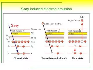
5.5 Theoretical explanations of electron emission at low applied fields 5.5.5 Particles on the electrode surface Good and Muller explained the high current emission density from absorbed particles or oxide crystals on a clean tungsten tip by the potential well model shown in Fig 5.7 In an insulating particle the energy bands are separated by a large energy gap or forbidden band. The main feature in Fig 5.7 is then a forbidden energy band in the actual adsorbed particle at the Fermi level, above which are unoccupied levels. The external field tilts the potential-well, so that the empty levels can be filled by electrons tunnelling from the metal. The two potential barriers are considerably smaller than the one in front of a plain metal surface at the same external field so the emission current is considerably enhanced. If the oxide crystal is sufficiently thick, the outer potential peak may fall below the Fermi level and the emission density then becomes even higher.
5.5 Theoretical explanations of electron emission at low applied fields 5.5.4 Hot spots Morant, who favoured the Schottky relationship to explain emission, suggested that the emission observed might arise at small hot spots(~10-5 cm2 in area) on the cathode, locally heated to about 500 ℃ by bombardment of the surface by the positive ions produced in initial discharges occurring in the gap. However, Nicholas showed that, for the results on which Morant based his calculations, the temperature of any small bombarded area would be room temperature. 5.5.5 Temperature-corrected field emission Murphy and Good derived the following equation to correct the emission values for temperature:
5.5 Theoretical explanations of electron emission at low applied fields There J(T1) and J(T2) are the emission currents obtained at temperatures T1 and T2 at a constant field strength that there is no change in work function with temperature, and KT1 is equal to K8T1/sinK8T1 Llewllyn-Jones and Nicholas measured the emission from gold at 197 and 298 K and showed that the current ratios for different temperatures were in close agreement with those predicted by this modified field-emission equation. 5.5.6 Microprojections In many tests they determined that the emission could be explained in terms of the field emission relationship provided that a value for the intensification factor m of about 100 was assumed. Such a value would mean the existense on the surface of very sharp microprojections. To check this possibility they located the emission sites on several optically polished electrically stressed cathodes by viewing the cathode surfaces through a transparent conducting anode with an optical microscope. These cathodes were then transferred to a shadow-electron microscope and in each case the emitting area was found to be the site of a needle-like projection. The projections were typically 2um high with a ratio of height to base diameter of about 10, this shape being sufficient to produce the required intensification factor of 100.