LHeC Linac-Ring Design
LHeC Linac-Ring Design. Alex Bogacz for the LHeC Study Group. Linac-Ring LHeC – two options. 60-GeV recirculating linac with energy recovery. straight linac. Roadmap to 10 33 cm -2 s -1 Luminosity. Frank Zimmermann. r ound beams. average e - current !. highest proton

LHeC Linac-Ring Design
E N D
Presentation Transcript
LHeC Linac-Ring Design • Alex Bogacz • for the LHeC Study Group DIS'11, Newport News, April 12, 2011
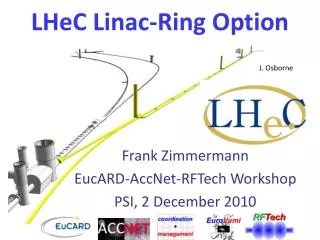
Linac-Ring LHeC – two options 60-GeV recirculating linac with energy recovery straight linac DIS'11, Newport News, April 12, 2011
Roadmap to 1033 cm-2s-1 Luminosity Frank Zimmermann round beams average e- current ! highest proton beam brightness “permitted” (ultimate LHC values) ge=3.75 mm Nb=1.7x10¹¹ bunch spacing 25 or 50 ns • maximize geometric • overlap factor • head-on collision • small e- emittance • qc=0 • Hhg≥0.9 • smallest conceivable • proton b* function: • reduced l* (23 m → 10 m) • squeeze only one p beam • new magnet technology Nb3Sn • b*=0.1 m DIS'11, Newport News, April 12, 2011
Pulsed linac for 140 GeV 7.9 km IP 140-GeV linac dump injector 0.4 km final focus • linac could be ILC type (1.3 GHz) or 720 MHz • cavity gradient: 31.5 MV/m, Q=1010 • extendable to higher beam energies • no energy recovery • with 10 Hz, 5 ms pulse, Hg = 0.94, Nb = 1.5x10⁹ : <Ie> = 0.27 mA → L ≈ 4x1031 cm-2s-1 DIS'11, Newport News, April 12, 2011
Linac-Ring Configuration J. Osborne J. Osborne Baseline: Energy Recovery Linac 60 GeV, Power 100MW total circumference ~ 8.9 km DIS'11, Newport News, April 12, 2011
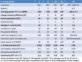
Design Parameters DIS'11, Newport News, April 12, 2011
Energy Recovering Linacs (ERL) • High energy (60 GeV), high current (6.4 mA) beams: (384 MW beam power) would require sub GW (0.8 GW)-class RF systems in conventional linacs . • Invoking Energy Recovery alleviates extreme RF power demand (power reduced by factor (1 -hERL) ⇨ Required RF power becomes nearly independent of beam current. • Energy Recovering Linacs promise efficiencies of storage rings, while maintaining beam quality of linacs: superior emittance and energy spread and short bunches (sub-pico sec.). • GeV scale Energy Recovery demonstration with high ER ratio (hERL = 0.98) was carried out in a large scale SRF Recirculating Linac (CEBAF ER Exp. in 2003) • No adverse effects of ER on beam quality or RF performance: gradients, Q, cryo-load observed – mature and reliable technology (next generation light sources) DIS'11, Newport News, April 12, 2011
~ 1 GeV Accelerating beam ~ 55 MeV Decelerating beam CEBAF ER Exp. 2003 RF Response to Energy Recovery 250 ms without ER with ER DIS'11, Newport News, April 12, 2011
LHeC Recirculator with ER Linac 1 0.5 GeV 10 GeV/pass Arc1, 3, 5 Arc 2, 4 Arc 6 Linac 2 10 GeV/pass IP 60.5 GeV LHC DIS'11, Newport News, April 12, 2011
Linac RF parameters DIS'11, Newport News, April 12, 2011
Required Power & Cryo-load DIS'11, Newport News, April 12, 2011
RF cavities Ilan Ben-Zvi DIS'11, Newport News, April 12, 2011
5 150 0.5 BETA_X&Y[m] PHASE_X&Y DISP_X&Y[m] 0 0 0 0 BETA_X BETA_Y DISP_X DISP_Y 56 0 Q_X Q_Y 56 Linac Optics - 1300 FODO Cell E = 0.5 GeV phase adv/cell: Dfx,y= 1300 2×8 cavities 2×8 cavities 720 MHz RF: Lc =100 cm 5-cell cavity Grad = 17.361 MeV/m DE= 555.56 MV linac quadrupoles Lq=100 cm GF= 0.103 Tesla/m GD= -0.161 Tesla/m DIS'11, Newport News, April 12, 2011
5 200 BETA_X&Y[m] DISP_X&Y[m] 0 0 0 BETA_X BETA_Y DISP_X DISP_Y 1008 Linac 1 - Focusing profile E = 0.5 - 10.5 GeV quad gradient 18 FODO cells (18 × 2 × 16 = 576 RF cavities) DIS'11, Newport News, April 12, 2011
5 500 BETA_X&Y[m] DISP_X&Y[m] 0 0 0 BETA_X BETA_Y DISP_X DISP_Y 1008 0.5 PHASE_X&Y 0 0 Q_X Q_Y 1008 Linac 3 (Linac 1, pass 2) - Optics E = 20.5 - 30.5 GeV betatron phase advance DIS'11, Newport News, April 12, 2011
5 200 BETA_X&Y[m] DISP_X&Y[m] 0 0 0 BETA_X BETA_Y DISP_X DISP_Y 1008 Linac 2 - Focusing profile E = 10.5 - 0.5 GeV (ER) quad gradient 18 FODO cells (18 × 2 × 16 = 576 RF cavities) Linac 2 multi-pass optics with ER - mirror symmetric to Linac 1 DIS'11, Newport News, April 12, 2011
5 800 5 800 BETA_X&Y[m] DISP_X&Y[m] BETA_X&Y[m] DISP_X&Y[m] 0 0 0 0 0 BETA_X BETA_Y DISP_X DISP_Y 6048 0 BETA_X BETA_Y DISP_X DISP_Y 6048 Linac 1 and 2 - Multi-pass ER Optics Linac 2 Linac 1 40.5 GeV 20.5 GeV 60.5 GeV 0.5 GeV 0.5 GeV 60.5 GeV 40.5 GeV 20.5 GeV 50.5 GeV 10.5 GeV 10.5 GeV 50.5 GeV 30.5 GeV 30.5 GeV DIS'11, Newport News, April 12, 2011
5 1500 BETA_X&Y[m] DISP_X&Y[m] 0.5 1500 0 0 0 BETA_X BETA_Y DISP_X DISP_Y 1008 BETA_X&Y[m] DISP_X&Y[m] -0.5 0 0 BETA_X BETA_Y DISP_X DISP_Y 1008 ‘weak’ vs ‘strong’ Linac focusing E = 0.5 - 10.5 GeV Zero quad gradient Wake field effects more severe ~ 8 times Daniel Schulte 1300 FODO DIS'11, Newport News, April 12, 2011
ERL configuration total circumference ~ 8.9 km Daniel Schulte DIS'11, Newport News, April 12, 2011
150 0.3 BETA_X&Y[m] DISP_X&Y[m] -0.3 0 0 BETA_X BETA_Y DISP_X DISP_Y 52.3599 Quasi-isochronous FMC Cell Emittance dispersion 〈H〉avereged over bends Momentum compaction factor of 2.5 smaller than FODO factor of 27 smaller than FODO DIS'11, Newport News, April 12, 2011
500 0.5 500 500 0.5 0.5 BETA_X&Y[m] DISP_X&Y[m] BETA_X&Y[m] BETA_X&Y[m] DISP_X&Y[m] DISP_X&Y[m] -0.5 -0.5 -0.5 0 0 0 0 BETA_X BETA_Y DISP_X 52.3599 DISP_Y 0 BETA_X BETA_Y DISP_X DISP_Y 52.3599 0 BETA_X BETA_Y DISP_X 52.3599 DISP_Y Arc Optics – Emittance growth Arc 1 , Arc2 Arc 3 Arc 4 , Arc5, Arc 6 Imaginary gt Optics TEM-like Optics DBA-like Optics factor of 18 smaller than FODO total emittance increase (all 5 arcs): DexN = 1.25 × 4.5 mm rad =5.6 mm rad emittance growth due to disruption in the collision 15%-180% (without/with rematch the outgoing optics) DIS'11, Newport News, April 12, 2011
Alternative Arc Optics - BNL FMC Cell Dejan Trbojevic Flexible Momentum Compaction DIS'11, Newport News, April 12, 2011
Recirculator Magnets • Proposed solution: • One type of bending magnets, possibly with different conductors • Two types of quadrupoles, same cross section, different length: Q2 1200 mm, Q0-Q1-Q3 900 mm; possibly with different conductors, radius 20 mm Davide Tommasini DIS'11, Newport News, April 12, 2011
Quadrupoles for 10 GeV Linacs 25 cm Davide Tommasini DIS'11, Newport News, April 12, 2011
Bending for 60 GeV Recirculator 23 cm Davide Tommasini DIS'11, Newport News, April 12, 2011
Quadrupoles for 60 GeV Recirculator 35 cm Davide Tommasini DIS'11, Newport News, April 12, 2011
Three-beam IR layout IR with a schematic view of synchrotron radiation – beam trajectories with 5 and 10 envelopes Half quadrupole with field-free region Stephan Russenschuck Rogelio Tomas DIS'11, Newport News, April 12, 2011
Vacuum requirements • The presence of a strong synchrotron radiation has two major implications for the vacuum system: • it has to be designed to operate under the strong photon-induced stimulated desorption while being compatible with the significant heat loads onto the beam pipes. • synchrotron radiation will dramatically enhanced the electron cloud build-up and mitigation solutions shall be included at the design stage. • Photon-induced desorption rate depends on critical energy of the synchrotron • light • E0 = 5.10-4GeV for electrons, EB is the energy of the beam and R the bending radius • For the Linac-Ring option (bending sections and by-passes), the linear photon flux is expected to be 5 times larger than in LHC. Miguel Jimenez DIS'11, Newport News, April 12, 2011
Vacuum mitigation • Scattering of particles on the molecules of the residual gas, dominated by the Bremsstrahlung on the nuclei of gas molecules ⇨ depends on partial pressure, weight of the gas species and radiation length • The beam-gas interactions are responsible for machine performance limitations such as; • reduction of beam lifetime (nuclear scattering) • machine luminosity (multiple Coulomb scattering) • intensity limitation by pressure instabilities (ionization) • Vacuum engineering issues • Pumping • Diagnostics • Sectorization • HOM and Impedance implications • Bake-out of vacuum system • Shielding Miguel Jimenez DIS'11, Newport News, April 12, 2011
Conclusions • High luminosity Linac-Ring option - ERL • RF power nearly independent of beam current. • Multi-pass linac Optics in ER mode • Choice of linac RF and Optics - 720 MHz SRF and 1300FODO • Linear lattice: 3-pass ‘up’ + 3-pass ‘down’ (single-pass wake-field effects) • Arc Optics Choice -Emittance preserving lattices • Quasi-isochronous lattices • Flexible Momentum Compaction • Acceptable level of emittance dilution & momentum spread • Magnet design • Quad and dipole prototypes • Vacuum requirements • Mitigations and engineering issues DIS'11, Newport News, April 12, 2011
Special Thanks to: Frank Zimmermann Daniel Schulte and Max Klein DIS'11, Newport News, April 12, 2011