Download
1 / 35
350 likes | 556 Vues
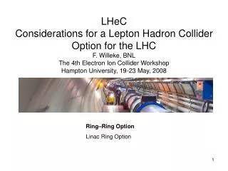
LHeC : Linac -Ring Option Hans-H. Braun / CERN General consideration Proton ring issues 70 GeV 140 GeV Polarisation and Positrons Comparison Ring-Ring v.s Linac Ring Conclusions. H.H. Braun, DIS08, 8.4.08. All considerations on LHeC linac-ring are in a very early stage,

E N D
LHeC : Linac-Ring Option • Hans-H. Braun / CERN • General consideration • Proton ring issues • 70 GeV • 140 GeV • Polarisation and Positrons • Comparison Ring-Ring v.sLinac Ring • Conclusions H.H. Braun, DIS08, 8.4.08
All considerations on LHeC linac-ring are in a very early stage, mainly parametric considerations to understand the potential of different options. Present plan is to establish collaborations to narrow down possible design choices and to work on critical issues with a first resume at LHeC workshop in September.
Physics requirements (more input welcome) e-p option has to co-exist with p-p, but not necessarily for simultaneous running. Dedicated running periods with special p-beam conditions like for present LHC heavy ion program can be envisaged if integrated luminosity sufficient. But technical modifications for LHeC should not compromise performance for p-p runs. e-A option comes automatically, since LHC is already prepared for operation with Pb208
Luminosity for ring linac hourglass effect p-beam parameters e-beam parameters
LHC P-beam parameters (“ultimate”) • Improvement of LHC proton parameters essential to get • more reasonable e-linacPBeam ! • Reduce proton b* • Increase proton bunch charge • Reduce proton emittance
Improvement of LHC proton parameters I • Reduction of proton b* Goal of present LHC IR upgrade R&D is to reduce b* from 55 cm to 25 cm for IR1 (ATLAS) and IR5 (CMS). For LHeC a IR with smaller L* could be envisaged, this allows for even smaller b* . We assume in the following b*=10cm. see also
Improvement of LHC proton parameters II • Increased proton bunch chargeNew LHC p-injector chain with LINAC 4, SPL and PS2 will allow to double NBatinjection of LHC. We assume therefore NB =3.4·1011
Improvement of LHC proton parameters III • Reduced proton emittanceNot very interesting for LHC p-p performance, but schemes for high energy proton beam cooling are under study elsewhere (BNL, FNAL) . • We assume that either with those schemes or with new LHC injectors P- emittance can be reduced by a factor 2
assumed LHeC p-beam parameters with b*=10cm, NB =3.4·1011 , eP=1.9mm still very high, but not completely out of scale
Power flow pulsed SC Linac Beam power Beam dump via cooling water to environment stored field energy RF load Grid power RF power generation cavity wall resisitivity Cryoplant cryostatstatic loss Example X-FEL 8 cavity Module (L=12.2m) Gain beam power (196MV*5mA*0.65ms*10Hz) 6.4 kW Grid power for RF stored field energy 19.3 kW Grid power for RF for beam acceleration 16.8 kW Grid power for static cryogenic losses 14.3 kW Grid power for dynamic cryogenic losses ~E2 13.1 kW overall efficiency 10% All overheads included !
Power flow c.w. SC Linac Beam power Beam dump via cooling water to environment Grid power RF power generation cavity wall resisitivity Cryoplant cryostatstatic loss Example X-FEL 8 cavity Module (L=12.2m), c.w. Gain beam power (196MV*32.5 A) 6.4 kW Grid power for RF stored field energy 0 kW Grid power for RF for beam 16.8 kW Grid power for static cryogenic losses 14.3 kW Grid power for dynamic cryogenic losses 857 kW overall efficiency 0.72% Example X-FEL 8 cavity Module (L=1pulsed case Gain beam power (196MV*5mA*0.65ms*10 6.4 kW Grid power for RF stored field energy 19.3 kW Grid power for RF for beam acceleration 16.8 kW Grid power for static cryogenic losses 14.3 kW Grid power for dynamic cryogenic losses ~ 13.1 kW overall efficiency 10%
Example X-FEL 8 cavity Module (L=12.2m), c.w. optimised for good power efficiency , gradient reduced to 11.8 MV/m, high c.w. current Gain beam power (98 MV*5mA) 490 kW Grid power for RF stored field energy 0 kW Grid power for RF for beam acceleration 1300 kW Grid power for static cryogenic losses 14.3 kW Grid power for dynamic cryogenic losses ~E2 214 kW overall efficiency 32% Example X-FEL 8 cavity Module ( nominal pulsed 23.6MV/m Gain beam power (196MV*5mA*0.65ms*10 6.4 kW Grid power for RF stored field energy 19.3 kW Grid power for RF for beam acceleration 16.8 kW Grid power for static cryogenic losses 14.3 kW Grid power for dynamic cryogenic losses ~ 13.1 kW overall efficiency 10% Example X-FEL 8 cavity Module (L=12. c.w. 23.6 MV/m Gain beam power (196MV*32.5 A) 6.4 kW Grid power for RF stored field energy 0 kW Grid power for RF for beam 16.8 kW Grid power for static cryogenic losses 14.3 kW Grid power for dynamic cryogenic losses 857 kW overall efficiency 0.72%
Good power efficiency in c.w. operation only achievable with high beam current and moderate accelerating field ! But for given Luminosity and energy beam current is given, i.e. IB=1.2 mA for L=1033cm-2s-1 Solution: recirculation as in CEBAF, S-DALINAC S-DALINAC
Recirculated superconducting c.w. Linac for LHeC Tentative parameter set for 1033cm-2s-1 Injector 1 GeV 0.75 km 1 km *here an uniform filling of LHC with proton bunches is assumed. Still needs to be adapted to real filling pattern. V=6 GeV LHC IP
Can this be combined with energy recovery scheme to reduce RF power and beam dump requirements ? Not easily, because of energy imbalance due to SR losses but this needs further studies. Dump Injector 1 GeV V=12 GeV 1.5 km 1 km LHC IP
6.3 GW c.w. beam power
For energies > 100 GeV only straight, pulsed linac, either superconducting or normal conducting can be considered
To be remembered: ERL’s don’t necessarily need arcs ! (as pointed out by SwapanChattopaday and Frank Zimmermann for LHeC context)
Parameters for pulsed Linacs for 140 GeV, 1032cm-2s-1 SC technology NC technology
Some remarks/questions • All the schemes discussed so far require p-bunch parameters whichare not compatible with LHC p-p running, i.e. require dedicatedLHeC running periods. • For the normal conducting linac case only proton bunches in about 5% of LHC circumference would collide. Luminosity comes in strong bursts of 4ms every 10 ms.How does this work for the detector ?
Some past work which has to be re-analysed in view of the new requirements arxiv.org/pdf/hep-ex/0504008
e± Linac - p/A Ringlocations alternative sites
Can tunnel for LHeCLinac be build as first part of a LC tunnel at CERN ? Tunnel studies for CLIC and ILC at CERN both have tunnels which are deeper underground than LHC and seen from top they both pass close to LHC ring center. Therefore they are not suited to send e- beam tangential to LHC ring. LHC tunnel CLIC tunnel
Injector issues, electrons • The electron, positrons are used only once in IP, therefore particle production rate for Linac-Ring option much higher than for Ring-Ring option. • Contrary to Ring Ring option beam polarisation has to be created from in source JLab has demonstrated production of polarised e- with > 61015 s-1 and >85% polarisation ! . Transport of polarised beam from source to IP with negligible loss of beam polarisation has been demonstrated in many facilities (SLC , CEBAF, MAMI, …)
Injector issues, positrons • Problem 1 • SLC has demonstrated e+ production of 1013 s-1 (unpolarised) • Linear colliders require 1014 s-1.This is already considered difficult to achieve ! • Positron recovery possible ? • There is ongoing R&D to produce polarized e+ at rates required for LC’s. • Two schemes under investigation: Helical undulator & Compton ring • Problem 2 • Beam emittance of beam from e.m. shower target is typically 2 orders of magnitude larger than electron source emittance. • emittance damping is required to match e+ beam size to P-beam size at IP. • Damping ring ? .
Comparison Linac-Ring and Ring-Ring Energy / GeV 40-140 40-80 Luminosity / 1032 cm-2 s-1 1-10 10 Mean Luminosity, relative 2 1 [dump at Lpeak /e] Lepton Polarisation 60-85% 30% [?] Tunnel / km 5-9 2.5=0.5 * 5 bypasses Biggest challenge positrons Civil Engineering Ring+Rf installation Biggest limitation luminosity (ERL ?) maximum energy IR not considered yet allows ep+pp one design? (eRHIC) 2 configurations [lox, hiq]
Conclusions • Ring-Linac solution can only achieve desired Luminosities withproton beam parameters adapted/upgraded for this purpose.A part of these proton upgrades is already part of the LHC upgrade R&D. • For ≤70 GeV a SC Linac with recirculation seems most attractive.If energy recovery is applicable and economically viable needs further studies.This has to be compared with ring-ring in terms of cost, power consumption and interference with p-p program. • For substantially higher energies recirculatedLinac and Ring-Ring are virtually excluded. Straight pulsed linac is only solution.If SC or NC linac technology is better choice needs further study.L >1032 cm-2s-1 seems extremely difficult for this case. • Positrons are a major R&D issue for ring-linac
Specific R&D for Ring-Linac • Positron production, polarization and perhaps recovery • IR region design • High power e- beam handling • p-beam optimisation for ring-linac • e- beam disruption in IP • p-beam stability, in particular for collision with pulsed linacs • Matching of p-beam time structure to cw and pulsed e- beams • RF design of linacs • Tunnel design
Many thanks for input and discussions to O. Bruening, H. Burkhardt, S. Chattopadhyay, J. Dainton, A. De Roeck, R. Garoby, M. Giovanozzi, M. Klein, T. Linnecar, V. Litvinenko, V. Mertens, J. Osborne, L. Rinolfi, D. Schulte, F. Zimmermann