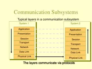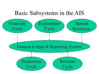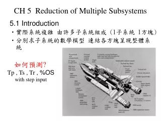
The Interconnection of two subsystems
The Interconnection of two subsystems. The Control Problems. Instability. Identification. RHP-zero. Time delay. The flow System. Valve position. Control Signal. The flow valve has integrator property. Static Identification and The Operating points of system.

The Interconnection of two subsystems
E N D
Presentation Transcript
The Interconnection of two subsystems K.N.Toosi University of Technology
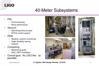
The Control Problems Instability Identification RHP-zero Time delay K.N.Toosi University of Technology
The flow System Valve position Control Signal The flow valve has integrator property K.N.Toosi University of Technology
Static Identification and The Operating points of system K.N.Toosi University of Technology
The Identification of a MIMO system should be achieved in MISO form • If the RGA matrix become If change to The system will be singular K.N.Toosi University of Technology
The most important problems for Identification • The excitation signals • should be Uncorrelated • Should be distinguished from output noise • Should not have the frequencies much more than actuator bandwidths • Should have a big range of frequency • Are Chirp in our experiments • The sample time is selected by these rules ; ; or to K.N.Toosi University of Technology
Input and output : • The transfer function • The effect of input flow on output level is small • The Disturbance model • This model has no delay K.N.Toosi University of Technology
Nominal model • The system with parametric Uncertainty : • Converting to unstructured uncertainty • Nominal Model for MIMO system K.N.Toosi University of Technology
Scaling • The scaling transfer function of plant and disturbance • The requirement for performance is |e(ω)| ≤1 for |u(ω)| ≤1, |r(ω)| ≤1 and |d(ω)| ≤1 • The max value of control signal 20 in flow Ch, and 30 in level Ch. K.N.Toosi University of Technology
Decentralized Control Based on Passive Approaches • Pairing • Avoid the Pairing correspond to negative RGA elements • The pairing is selected with RGA closed to unity • Design controller for each subsystem • There is no specific approach for this problem • Good phase and gain margin for each subsystem of nominal model • PI controller for each channel K.N.Toosi University of Technology
Stability Of Decentralized Control • A system with decentralized controller is stable if • Each subsystem is stable√ • Following inequality holds • Where and is the complementary sensitivity function of • If The system is closed two triangular this condition is always hold √ K.N.Toosi University of Technology
Performance Of Decentralized Control • Desired performance by disturbance input × • is the element of CLDG Matrix: , • Desired performance by reference input • Where is the element of PRGA matrix × Flow Level K.N.Toosi University of Technology
Step Response Of Decentralized Controller Control Signal step response • Settling time after 300 (sec) in both channels × • The control signal is in its range √ • The inverse response of non-minimum phase zero √ • Overshoot is about 50% in flow ch. × And less than 5% in level ch.√ K.N.Toosi University of Technology
Disturbance Rejection of Decentralized Controller Disturbance response Control Signal • Disturbance rejection after 170 (sec) in flow Ch. √ and 400 in level ch.× • The control signal is in its range. √ • The maximum peak of response about 25(lit/h) in flow ch. × and about 6.4(cm) in level ch. √ K.N.Toosi University of Technology
Uncertainty and Robustness • Uncertainty in Input or in output • The uncertainty is much more in MIMO systems • Uncertainty can be parametric or unstructured Output Uncertainty Input Uncertainty K.N.Toosi University of Technology
Nominal Model and Multiplicative uncertainty Z=1.7363 • Output Multiplicative Model: is the upper band of and K.N.Toosi University of Technology
The model Validation • In MIMO systems the gain of system varies between minimum and maximum singular value • The gain of system also can vary because of uncertainty K.N.Toosi University of Technology
Limitations on Performance • In MIMO systems each element has its own direction such as RHP-zero, RHP-Pole, disturbance, uncertainty and etc. • Effect of zero in MIMO system • There is no effect with input K.N.Toosi University of Technology
Waterbed Effect Theorem • In SISO systems • In MIMO systems • No special conclusion for MIMO system K.N.Toosi University of Technology
S T Limitation on S and T • S+T=I • We can not decrease both S and T Simultaneously • S is large if and only if T is large K.N.Toosi University of Technology
Interpolation Condition • for internal stability for the plant with no RHP-Pole and one RHP-zero • This condition restricts the performance weight K.N.Toosi University of Technology
Limitations By Time Delay • In SISO systems delay will limit the bandwidth • In MIMO systems, every output has at least the minimum delay of the elements in its own row • Delay may improve performance of MIMO systems K.N.Toosi University of Technology
Limitation By RHP zero • By using Maximum Modules Theorem • For tight control at low frequencies • For tight control at high frequencies K.N.Toosi University of Technology
Maximum Peak Criterion • The growing on maximum peak of sensitivity function cause to big overshoot • M more than 2 is not suitable • The phase margin of system will decrease K.N.Toosi University of Technology
Limitations Caused By Uncertainty • In each channel for robust performance it is required K.N.Toosi University of Technology
Limitations Caused By Disturbance • Condition number of plant and disturbance • A single disturbance with one RHP-zero • is the output direction of RHP-zero • Another condition Flow Level K.N.Toosi University of Technology
The Selection of Performance Weight • Performance weight in each channel • The selection of bandwidth • Restricting the overshoot K.N.Toosi University of Technology
The selection of Control Signal Weight • Performance Weight K.N.Toosi University of Technology
Robust Control Design • Integrator in each element of controller • The order of controller is equal to the states of generalized plant order • The controller is obtained by iterative algorithm K.N.Toosi University of Technology
The Generalized Plant in Our Problem • The infinity norm by considering disturbance in SISO system • Without consideration of disturbance K.N.Toosi University of Technology
The Step Responses Control signal Step response • Settling time 150 (sec) in both channels without considering disturbance √ and 200 in second one. √ • The control signal is in its range√ • The inverse response of non-minimum phase zero √ • The Overshoot is about 15% in flow ch. √ and 5% in level ch. √without considering disturbance and more than 40% for the controller by considering disturbance× K.N.Toosi University of Technology
Disturbance Responses • Disturbance rejection after 170 (sec) for both controllers in flow ch.× • Disturbance rejection after 200 (sec) in controller with disturbance model and 300(sec) in another controller in level ch.× • The control signal is in its range. √ • The maximum peak of response 20(lit/h) in flow ch. with disturbance model× and 25(lit/h) for another controller√ • The maximum peak of response 5.7(cm) √ and about 7(cm) for another controller in level ch.. √ K.N.Toosi University of Technology
Robust Stability • Sufficient Condition • Necessary and Sufficient Condition K.N.Toosi University of Technology
Nominal Performance K.N.Toosi University of Technology
Robust Performance K.N.Toosi University of Technology
µ-Analysis for Robust Performance • Max Peak of µ: • 1.2544 without disturbance model • 1.7257 in second design • Too large for Decentralized controller K.N.Toosi University of Technology
μ-Synthesis and DK-Iteration • Step K: Design a controller such that • Step D: Find D such that following equation become minimum K.N.Toosi University of Technology
Step Response for DK-Iteration Controller • Settling time after 150 (sec) in both channels • The control signal is in its range√ • The inverse response of non-minimum phase zero × • The overshoot less than 15% in both outputs√ • The order of controller is 16 K.N.Toosi University of Technology
Disturbance Response for DK-Iteration Controller Step Response Control Signal • Disturbance rejection after 200 in flow Ch. √ and 300 in level channel × • The control signal is in its range√ • The maximum peak of response 13(lit/h) in flow ch. √ and 5.7(cm) in level ch. √ K.N.Toosi University of Technology
Controller Order Reduction Flow Level • Coprime factorization • Balanced Residualization • Balanced Truncation K.N.Toosi University of Technology
Conclusions: • Decentralized controller for the systems with small interactions and performance is not important problem • Obtaining uncertainty for MIMO systems is hard • Useful tool for analyzing the robustness of the system • The induced norm can represent many properties of system • High order of H∞ controller and order reduction K.N.Toosi University of Technology
Suggestions: • The position of valve(3) can be rearranged to have more interaction • Designing controller by considering input uncertainty • Designed Controller by considering parametric uncertainty • The structure of controller can be determined by designer • The QFT robust controller combined with decentralized control approaches . • Fetching control signal in saturation K.N.Toosi University of Technology
Acknowledgment K.N.Toosi University of Technology