Download
1 / 31
380 likes | 673 Vues
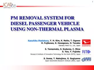
PM REMOVAL SYSTEM FOR DIESEL PASSENGER VEHICLE USING NON-THERMAL PLASMA. Kazuhiko Madokoro , Y . H. Kim, K. Naito, T. Ogawa H. Fujikawa, K. Hasegawa, H. Tanaka. Daihatsu Motor Co., Ltd., Japan. S. Yamamoto, S. Kodama, C. Mine S. Yao, Y. Fujioka.

E N D
PM REMOVAL SYSTEM FOR DIESEL PASSENGER VEHICLEUSING NON-THERMAL PLASMA Kazuhiko Madokoro, Y. H. Kim, K. Naito, T. Ogawa H. Fujikawa, K. Hasegawa, H. Tanaka Daihatsu Motor Co., Ltd., Japan S. Yamamoto, S. Kodama, C. Mine S. Yao, Y. Fujioka Research Institute of Innovative Technology for the Earth (RITE), Japan S. Soma, T. Nakajima, G. Sugiyama Japan Automobile Research Institute (JARI), Japan
Outline • Introduction - Diesel emission regulations - What is plasma? - Advantages and problems of plasma technology • Experimental • Results • Conclusion
Japanese JC08 mode Our target Diesel emission regulations (Passenger vehicles) Japan EU US 11, 10・15 , JC08 mode NEDC mode FTP mode PM [g/km] 1997 0.080 1994 Tier1 0.062 2002 2000 Euro3 0.052 0.05 2004~06 Tier2 (Bin#9) 0.037 2005 Euro4 0.025 2005 0.013 2007 Tier2 (Bin#5) 2009 Euro5 0.006 2009 0.005 0.005 0.18 0.25 0.5 0.044 0.19 0.78 0.14 0.28 0.08 0.4 NOx [g/km] NOx [g/km] NOx [g/km] • Stricter regulations for emission control are being set all over the world. • The Japanese post new long-term emission regulation comes into force. • A newly established emission test mode (JC08) has also been introduced.
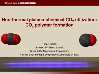
Discharge plasma CO2 CO PM O3, O, NO2 etc What is Plasma ? Lightning Aurora • Plasma is called a "Fourth State of Matter". • Plasma is a partially ionized gas mixture and contains electrons, ions, neutral atoms, molecules, reactive free radicals and photons. Three states of matter Fourth state Solid Liquid Gas Plasma Electrolytic dissociation Melting Evaporation Application of the plasma to diesel exhaust gases It is generally known that highly reactive species such as O3, O, NO2 and OH are generated in the plasma of diesel exhaust gases. These reactive species can lead to oxidation of PM. Exhaust gases O2, NO, H2O etc
PM emission : below 0.005 g/km Pressure drop: below 5 kPa Fuel penalty : below 2.5% (at Japanese JC08 mode) Advantages and problems of plasma technology • Advantages • Successive PM removal irrespective of ambient temperature • No using Platinum-Group Metals • Easily controllable of PM removal rates by power management • Simple reactor configuration for low pressure drop • Hurdles to overcome before practical use • Designing of a novel plasma reactor • Reduction of energy consumption • Improvement of power supply system & power delivery for plasma generation • Elucidation of PM removal mechanism • Durability of the system Target
Outline • Introduction • Experimental - Discharge system - Emission measurement system - Modal emission test • Results • Conclusion
Discharge system High voltage probe Oscilloscope Current Transformer Pulse Power Supply Discharge DC Power Supply Plasma Reactor AC 100V Ref: S. Yao (RITE), AIChE J., Vol. 53, 1891-1897 (2007) Dielectric barrier discharge reactor driven by high-voltage pulses
Non-thermal plasma reactor Dielectric plate Electrode High voltage Earth Gas flow Oxidation (Combustion) Electrode Temporary trap PM (c) CO2 (CO) Gas flow Dielectric (General flat plate of alumina)
Emission measurement system PM mass emission Chassis dynamometer Soluble organic fraction (SOF) Insoluble organic fraction (ISF) Soxhlet extraction Sampling bag PM filter CFV-CVS Dilution Air Full flow dilution tunnel Dilutor Vehicle data Engine Exhaust Particulate Sizer (EEPS-3090) Particle number concentration Vehicle emission measurement was carried out at JARI.
Modal emission test • Japanese JC08 mode (hot and cold start) Warm-up period Hot mode start Cold mode start (without warm-up) Emission measurement start • Evaluated aftertreatment system Without aftertreatment Engine Original aftertreatment (DOC) Engine DOC Original & Plasma reactor Engine Plasma reactor DOC
Outline • Introduction • Experimental • Results - Inlet gas temperature of the plasma reactor - PM mass emission - Particle size distributions - Appearance of alumina plates - Pressure drop of plasma reactor • Conclusion
Inlet gas temperature of the plasma reactor Gas temperature • Cold start mode Maximum : 222.0 ºC Average : 147.0 ºC • Hot start mode Maximum : 222.6 ºC Average : 170.4 ºC • Inlet gas of the plasma reactor was under low temperature during mode.
91% (0.0048 g/km) 51% 62% 59% 15% 23% 26% 86% 91% 93% 77% 79% 81% 79% 84% 86% 54% 35% 23% PM mass emission * Combine emission = Cold mode emission × 0.25 + Hot mode emission × 0.75 Hot Combine* Cold Japanese new regulation (JP 2009) • The plasma reactor showed almost same removal capability in both modes. • The oxidative ability of plasma showed elective affinity for soot. • PM emission of our plasma reactor achieved JP2009 regulation (combine emission value 0.0048 g/km).
w/o aftertreatment w/o aftertreatment Original Original w/o aftertreatment w/o aftertreatment Original Original Original & Plasma Original & Plasma 81.3% 87.6% Good Particle size distributions Cold Hot • Particle concentrations after the plasma reactor were clearly reduced. • Non-thermal plasma could also remove nano-particles.
Appearance of alumina plates Without plasma With plasma Temporary trap Exhaust gas flow Oxidation (Combustion) After about 300 km mode driving Area of electrode • PM was clearly removed on the alumina plate with plasma. • PM adsorption was observed less at downstream side. It is suggested that reactive species which came from the upstream side contributed to oxidize PM at the downstream side.
Pressure drop of the plasma reactor • The plasma reactor maintained lower pressure drop during consecutive mode tests. • It is suggested that PM was successively removed by the plasma reactor.
Conclusion 1. PM emission could satisfy JP2009 emission regulation of 0.005 g/km by installing the plasma reactor after the original DOC. The plasma reactor showed successive high removal rate for ISF which is not easily oxidized with catalytic reactions compared with SOF. 2. The plasma reactor could remove PM under low temperature. Such a removal ability is a great advantage compared with a catalyst or a DPF which requires active regeneration. 3. The plasma reactor showed low pressure drop during JC08 mode. Such low pressure drop was achieved due to the structural characteristic of plasma reactor. This plasma system is expected to be one of the promising technologies for diesel emission control.
Acknowledgement This work is supported by Japanese government through NEDO. New Energy Industrial Technology Development Organization Comprehensive Technological Development of Innovative, Next-Generation, Low-Pollution Vehicles R&D of Innovative After-Treatment Systems We would like to thank Professor Yoshimasa Nihei [Tokyo University of Science] Professor Hajime Fujimoto [Doshisha University] Professor Yoichi Hori [The University of Tokyo] Professor Yasutake Teraoka [Kyushu University] Thank you for your attention !
NOx emission Hot Cold Combine
High voltage probe Oscilloscope Current Transformer Pulse Power Supply DC Power Supply Plasma Reactor AC 100V Discharge system DC powersupply (DC voltage : 0-600V) Pulse power supply driven by DC power supply (Pulse peak voltage : ~ 10kV)
Glass wool spacer New electrode Alumina plate (dielectric) Gas flow Gas flow Plasma reactor and new electrode Discarge PM Ref: S. Yao (RITE), AIChE J., Vol. 53, 1891-1897 (2007) Gas flow Electrode Electrode Dielectric (Mass-produced flat plate of general alumina)
Dielectric Barrier Discharge Pulsed Corona(+) wire cylinder rod barrier cylinder Thermal and Non-thermal plasma 106 Line of Tgas Telectron 105 ne ~ 1018cm-3 104 Arc ne ~ 1015cm-3 MW Torch Gas Temperature Rise [C] 103 RF Jet ne ~ 1012cm-3 102 Pulsed Corona & DBD ne ~ 1012cm-3 101 MH Cho, postech, 8th APCPST, 2006 0 5 10 15 20 Electron Temperature [eV] • Thermal plasma : All particles are in state of high temperatures. Gas show high temperatures. • Non-thermal plasma : Only electrons show high temperatures. Gas remains in state of almost 'cold' (ambient temperature).
Our concept for reducing each emissions NOx reduction NOx reduction Cooled EGR 2CD NOx catalyst Plasma Reactor DOC CO, HC and SOF reduction Soot and SOF reduction • NOx is reduced by control of engine combustion or NOx catalyst. • CO, HC and SOF are reduced by the diesel oxidation catalyst. • Soot and SOF are reduced by the plasma reactor.
Equation for PM removal rates ー Emission w/ o aftertreatment Original or Original & Plasma emission PM removal rate from emission w/o aftertreatment = × 100 (%) Emission w/ o aftertreatment ー Original DOC emission Original & Plasma emission PM removal rate from original DOC emission = × 100 (%) Original DOC emission
PM number emission (CPC) Cold Hot Combine
Japanese 10-15 mode and JC08 mode • Japanese 10-15 mode • Japanese JC08 mode
Gas temperature • Cold start mode Maximum : 222.0 ºC Average : 147.0 ºC • Hot start mode Maximum : 222.6 ºC Average : 170.4 ºC Pressure drop • Cold start mode Maximum : 3.4 kPa • Hot start mode Maximum : 3.8 kPa Gas temperature and pressure drop • The plasma reactor could remove PM effectively even under low temperatures. • The plasma reactor showed lower pressure drop below 3.8 kPa during mode.
PM mass emission (JP2009) Combine emission value 0.0038 g/km * Combine emission = JC08 Cold mode emission × 0.25 + 10-15 Hot mode emission × 0.75 Hot (10-15) Combine* Cold (JC08) Japanese new regulation (JP 2009)
Fluctuation of pressure drop during mode tests • Maximum pressure drop didn't increase during consecutive mode tests. • It is suggested that PM was successively removed by the plasma reactor.